


-
Wireless power transfer (WPT) has emerged as a transformative technology with diverse applications, including electric vehicle charging, medical devices, and consumer electronics, due to its ability to overcome the constraints of wired power transfer, offering enhanced flexibility and convenience[1−5]. The increasing adoption of WPT systems highlights their potential to revolutionize power delivery; however, significant challenges remain in ensuring stable and efficient power transmission under varying load and spatial alignment conditions. A particularly critical issue is maintaining a constant voltage output despite fluctuations in load or misalignment of coils, both of which are prevalent in practical implementations and dynamic real-world environments. Addressing these challenges is essential for advancing WPT systems into broader and more reliable applications.
WPT systems often rely on load-dependent topologies, which are inherently sensitive to variations in load impedance[6−10]. For example, in UAV systems, energy is transmitted through a combination of emitter plates, with the UAV's position determined by analyzing input and output parameters via a communication link. This allows for the selection of the optimal emitter configuration for efficient energy transfer[11]. Similarly, WPT technology is finding increasing use in consumer electronics, such as mobile phones, enabling convenient, contactless charging solutions that enhance user experience and mobility[12].
These designs typically require frequent manual tuning or component adjustments to maintain consistent and optimal performance. However, under fluctuating load conditions, their efficiency tends to degrade, limiting their practicality in dynamic real-world applications.
To overcome these limitations, recent research has focused on developing load-independent topologies that ensure stable power transfer without the need for continuous tuning. Among these, Class EF inverters have gained attention for their ability to maintain zero-voltage switching (ZVS) under variable load conditions. ZVS minimizes switching losses by preventing the dissipation of energy stored in the parasitic capacitance at the main junction of the active device, thereby significantly improving overall system efficiency. Furthermore, in Class E circuits, ZVS is complemented by zero-voltage derivative switching (ZVDS), where the current through the active device at turn-on is zero[10,13−16]. This results in a zero rate of change of voltage across the parasitic capacitor, further reducing energy losses and enhancing system performance[17].
Unmanned aerial vehicles (UAVs) are inherently small in size to meet the demands for high flexibility and mobility. However, the development of a reliable, efficient, and simple wireless power transfer (WPT) system capable of providing a constant voltage output under varying load conditions and low coupling coefficients remains a significant challenge.
To address this, a high-frequency resonant WPT system is proposed in this study, featuring a load-independent Class EF inverter. The system is specifically designed to deliver a constant voltage output even at low coupling factors while maintaining zero-voltage switching (ZVS) across a wide range of load conditions. This eliminates the need for manual regulation or component tuning, ensuring both load-independence and ZVS operation over diverse operating scenarios.
The proposed WPT system operates at a frequency of 6.78 MHz and has been rigorously tested under various load and spatial offset conditions using simulation tools like LT-Spice. Experimental results validate the system's ability to consistently maintain a constant voltage output and achieve ZVS. This research provides a practical and efficient WPT solution that addresses the limitations of conventional load-dependent systems, offering stable power delivery regardless of load variations or coil misalignments.
-
For the circuit in Fig. 1, the rectifier section can be simplified by neglecting parasitic elements, reducing it to an equivalent DC impedance. The system facilitates soft switching and maintains a constant output current amplitude regardless of the load resistance (Rload), as shown in Fig. 1a. Figure 1b depicts the topology of the load-independent Class EF inverter commonly employed in high-frequency wireless power transfer (WPT) systems. This inverter achieves optimal performance through key features such as load-independent constant voltage output and zero-voltage switching (ZVS).
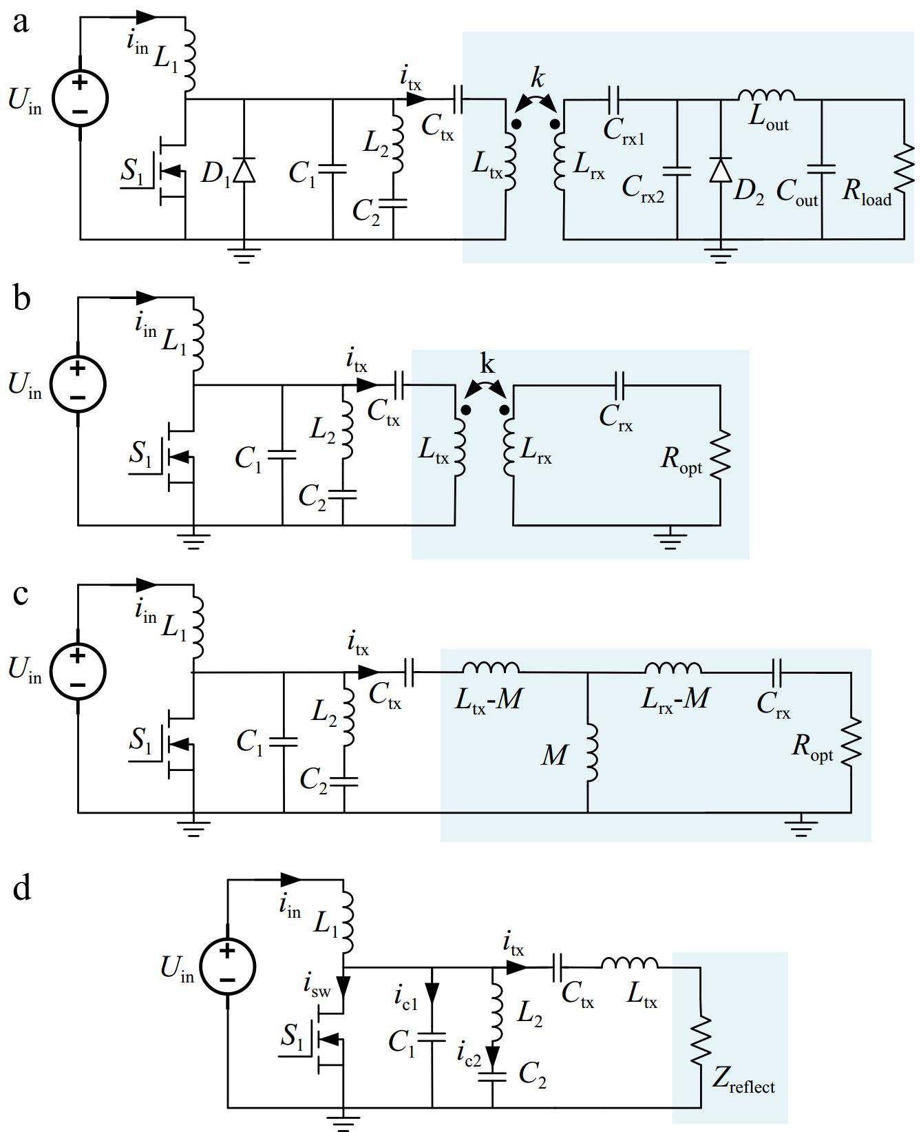
Figure 1.
Circuit of load-independent WPT system design.
The circuit comprises an input voltage source (Uin), a resonant tank formed by inductors (L1, L2, Ltx, Lrx), capacitors (C1, C2, Ctx, Crx), and a switching element (S1). Critical operating parameters include the switching duty cycle (D) and the coupling coefficient (k) between the transmitter and receiver coils. The series LC network, consisting of inductor L2 and capacitor C2, is designed to resonate at a frequency (ω2) that lies between the switching frequency (ω1) and its second harmonic (2ω1).
The system is then equivalently simplified, as depicted in Fig. 1b and c. This simplification allows the system to be further reduced, ultimately resulting in the equivalent circuit shown in Fig. 1d. The design methodology underscores the versatility of Class EF and Class E configurations in achieving load-independent performance, which is crucial for robust WPT systems.
In the present work, a mathematical model of the load-independent Class EF inverter, which outputs a constant current magnitude and phase, is developed, employing a methodology analogous to that used for the load-independent Class E inverter. Notably, due to the duality relationship between the load-independent rectifier and the inverter, the design parameters of the load-independent rectifier can be directly applied to the load-independent inverter's design. This dual relationship enables the transfer of parameter selection principles from the load-independent Class E rectifier to the Class E inverter, thus providing a coherent approach to the design and analysis of the system. To simplify theory analysis, several assumptions are made:
(1) The switching devices S1 are ideal, with zero on-state resistance and infinite off-state resistance, and all passive components are lossless.
(2) The switches operate such that S1 is ON during 0 < ωt ≤ 2πD and OFF during 2πD < ωt ≤ 2π, with the transition to the OFF state occurring rapidly.
3. Additionally, the output filter, with a characteristic impedance
$ \sqrt{\dfrac{{L}_{tx}}{{C}_{tx}}} $ $ \phi $ $ \phi $ These assumptions facilitate the analysis of the EF-class inverter, focusing on its resonant network design, constant current output, and efficient operation. Aldhaher et al.[18] provides a comprehensive analysis of EF-class inverters and derives the general form of equations describing the inverter voltage and current characteristics. Here, we present only the final form of the equations specifying load-independent operating conditions, along with relevant definitions. To simplify the theoretical analysis, the ZVS condition and load-independent operation are derived based on two key constraints, which are discussed in subsequent sections:
$ \left|{v}_{sw}\left(2{\text π} \right)\right|\le {\varepsilon }_{1} $ (1) Equation (1) ensures that the switch voltage transitions to zero before the switching event occurs, thereby achieving zero-voltage switching (ZVS). Maintaining ZVS minimizes switching losses and improves the overall system efficiency, particularly in high-frequency operations.
$ \left|\dfrac{\partial {i}_{tx}}{\partial {Z}_{reflect}}\right|\le {\varepsilon }_{2} $ (2) Equation (2) represents the core condition for ensuring load independence in the system. It implies that variations in the reflected impedance Zreflect due to changes in the load Rload have minimal impact on the transmitter coil current itx. This is crucial for achieving a stable and consistent output voltage across a wide range of load variations.
Under these conditions, ε1 and ε2 are set as small positive values rather than zero, thereby expanding the solution space and enhancing the system's tolerance to component variations. Due to the complexity of deriving an analytical solution for the governing equations, numerical methods were employed to solve for the key variables. This approach subsequently enabled the derivation of explicit expressions to simplify the analysis of the circuit's operation. Consequently, Kirchhoff's Current Law (KCL) and Kirchhoff's Voltage Law (KVL) equations, along with the reflected impedance (Zreflect), can be formulated with ease, streamlining the evaluation of the circuit's performance.
$ \begin{array}{c}{v}_{sw}\left(\omega t\right)={v}_{{c}_{1}}\left(\omega t\right)=\left\{\begin{array}{*{20}{l}}{\displaystyle\int }_{2{\text π} D}^{\omega t}{i}_{{C}_{1}}dt,& 2{\text π} D \lt \omega t\le 2{\text π} \\ 0 ,& 0 \lt \omega t\le 2{\text π} D\end{array}\right.\end{array} $ (3) $ \dfrac{{i}_{{C}_{1}}}{{I}_{\text{in}}}\left(\omega t\right)=1-p\left(\alpha +1\right)sin\left(\omega t+\phi \right)-\dfrac{{i}_{{L}_{2}}}{{I}_{\text{in}}}\left(\omega t\right)$ (4) $ R_{opt}=\dfrac{1}{\dfrac{1}{2f_{\mathrm{s}\mathrm{w}}}}\left\{\displaystyle\int_0^{\frac{1}{2f_{\mathrm{s}\mathrm{w}}}}\dfrac{V_{\mathrm{o}\mathrm{u}\mathrm{t}}\ \times0.5\ \times {\text π}}{2I_{\mathrm{o}\mathrm{u}\mathrm{t}}}\mathrm{sin}\left(\omega t\right)dt\right\}=wL_1\times R_{load} $ (5) $ \begin{split}{Z}_{reflect}=\;&\dfrac{{M}^{2}R{w}^{4}{c}_{\mathrm{r}\mathrm{x}}^{2}}{{R}^{2}{w}^{2}{c}_{\mathrm{r}\mathrm{x}}^{2}+{\left(1+{w}^{2}{c}_{\mathrm{r}\mathrm{x}}{L}_{\mathrm{r}\mathrm{x}}\right)}^{2}}\\ &-i\left\{\dfrac{{M}^{2}{w}^{3}{c}_{rx}}{{R}^{2}{w}^{2}{c}_{rx}^{2}+{\left(1+{w}^{2}{c}_{rx}{L}_{rx}\right)}^{2}}+\dfrac{{M}^{2}{w}^{5}{c}_{rx}^{2}{L}_{rx}}{{R}^{2}{w}^{2}{c}_{rx}^{2}+{\left(1+{w}^{2}{c}_{rx}{L}_{rx}\right)}^{2}}\right\}\end{split} $ (6) The zero-voltage switching (ZVS) condition and the load-independent condition are both critical for ensuring high efficiency and stable operation of the inverter. By differentiating the governing equations, the solution space for these two fundamental conditions can be derived. To facilitate optimal parameter selection and enable a more detailed classification, the following parameters are defined. This approach provides a deeper understanding of the system's characteristics and aids in refining the inverter's design and performance analysis.
$ \alpha =\dfrac{{C}_{1}}{{C}_{2}} $ (7) $ \beta =\dfrac{{\omega }_{2}}{{\omega }_{1}} $ (8) $ \gamma =\dfrac{1}{\omega }\sqrt{\dfrac{{C}_{1}+{C}_{2}}{{L}_{2}{C}_{1}{C}_{2}}}=\beta \sqrt{\dfrac{\alpha +1}{\alpha }}$ (9) $ p=\dfrac{{C}_{2}}{{C}_{1}+{C}_{2}}\dfrac{{I}_{tx}}{{I}_{\mathrm{i}\mathrm{n}}}=\dfrac{1}{\alpha +1}\dfrac{{I}_{tx}}{{I}_{\mathrm{i}\mathrm{n}}} $ (10) -
The design objective is to develop a load-independent Class EF inverter for an inductive wireless power transmission (WPT) system. The primary coil is designed to provide an output current amplitude of 8 A at an operating frequency of 6.78 MHz. The reflected load resistance seen by the inverter is expected to range from a maximum of 5 Ω to a minimum of 0 Ω, while the coil inductance is specified as 2.25 μH, as Fig. 2 illustrates.
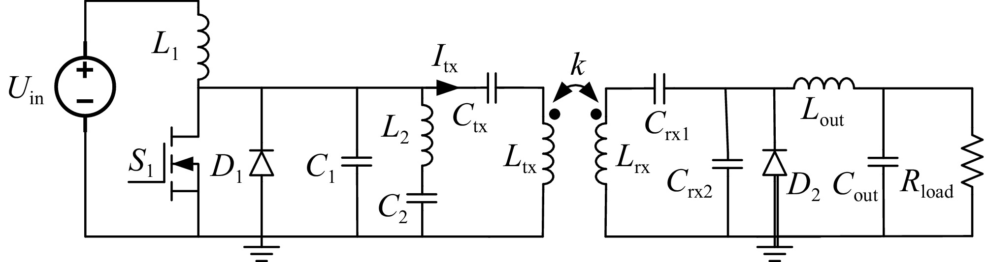
Figure 2.
Proposed 6.78 MHz load-independent WPT system.
The input voltage is determined at the point where the output capacitance of the switching device stabilizes. The selected switching device is the GS66508T MOSFET (650 V) from GaN Systems, chosen for its suitability in high-frequency operations. Using Eqns (1) and (2), the parameters ε1 and ε2 were set to 2%. The desired primary output current, input DC voltage, and maximum load resistance were combined and substituted into the equations to calculate a load factor (p) of 3 and a coupling coefficient (k) of 0.08. Subsequent calculations a capacitance C1 of 160 pF with Switch's Coss. Based on the calculated value of α, the capacitance C2 was determined to be 130 pF, and the inductance L2 was calculated as 500 nH.
A parameter scan using the derived equations confirmed an inductance of 2.25 μH. Capacitor Ctx was then calculated to resonate with this inductance at the switching frequency, resulting in a value of 310 pF. All calculated parameters are summarized in Table 1. This configuration ensures that the system components are optimally tuned for efficient operation within the specified design constraints.
Table 1. Parameters of the MIMO WPTN system.
Parameter Value Parameter Value Vin 100 v $ {C}_{out} $ 175 nf L1 33 μH $ {C}_{1} $ 160 pf L2 500 nH $ {C}_{2} $ 130 p Ltx 2.25 μH $ {C}_{tx} $ 310 p Lrx 266 nH $ {C}_{rx} $ 2.6 nf Lout 1.8 μH $ {C}_{rx2} $ 2.6 nf This setup ensures that the system components are tuned for efficient operation at the specified parameters.
After calculating all component parameters, a load-independent Class EF inverter was implemented in the WPT system. Figure 3 presents the simulated circuit diagram of the system. To evaluate the load-independent performance of the Class EF inverter, experiments were conducted by varying the electronic load. As shown in Fig. 4, the inverter maintains a constant current in the transmitter coil, resulting in an output voltage that remains nearly constant despite variations in the load. The waveforms demonstrate that the inverter consistently delivers an output current of 8 A across the entire input power range while sustaining zero-voltage switching (ZVS) operation. This confirms its ability to provide a constant voltage output and verifies its load-independent performance.
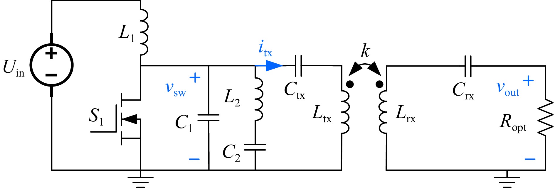
Figure 3.
Simulated circuit diagram of load-independent WPT system.
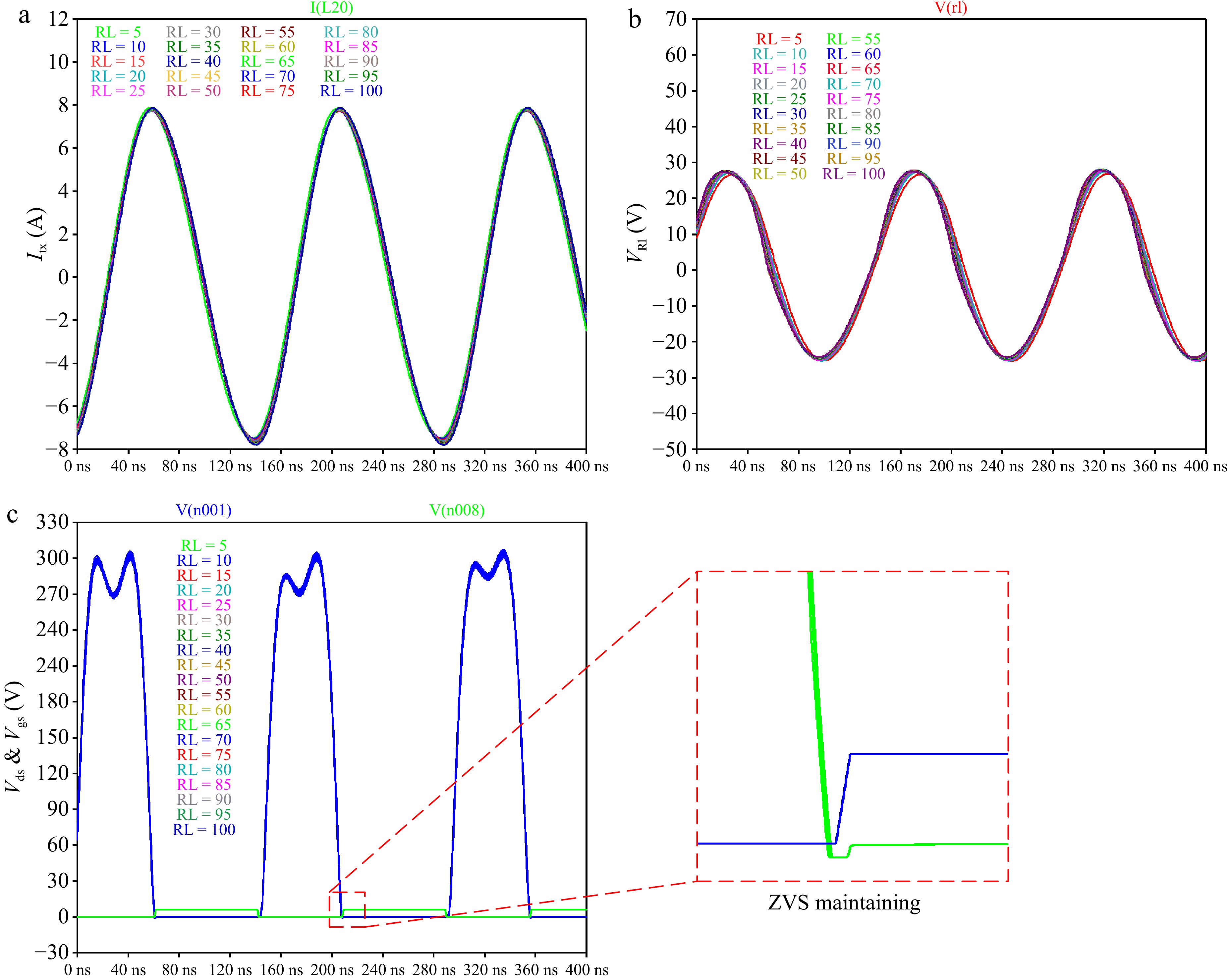
Figure 4.
Simulation TX current and drain-source voltage waveforms and output voltage.
-
Figure 5 illustrates the proposed high-frequency WPT system designed to deliver a load-independent constant output. The primary coil, represented by the inductor Ltx, consists of two turns of copper tubing with dimensions of 9 cm × 6 cm. The secondary coil, identical in dimensions to the primary coil (6 cm × 3 cm), is connected to a series capacitor (Ctx) to achieve resonance. This resonance provides a resistive impedance to the Class EF inverter, ensuring efficient and stable operation of the WPT system across a wide range of load conditions.
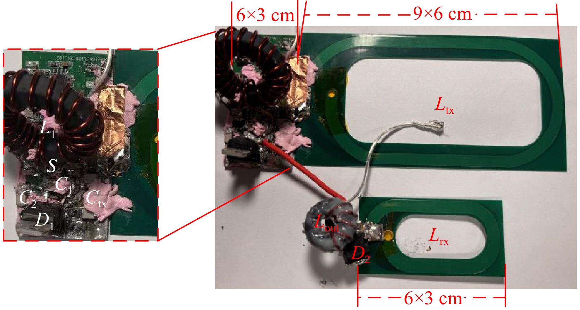
Figure 5.
Proposed load-independent WPT system.
Figure 6 illustrates the DC-DC efficiency as a function of load variation. The system achieves a peak efficiency of 84.6%, which accounts for gating losses between nodes, while maintaining a near-constant voltage (CV) output and sustaining full zero-voltage switching (ZVS) operation for load variations ranging from 10 to 50 Ω. As the load changes, the input power to the inverter gradually increases. The maximum output power of the inverter is 100 W, constrained by the thermal limitations of the MOSFETs.
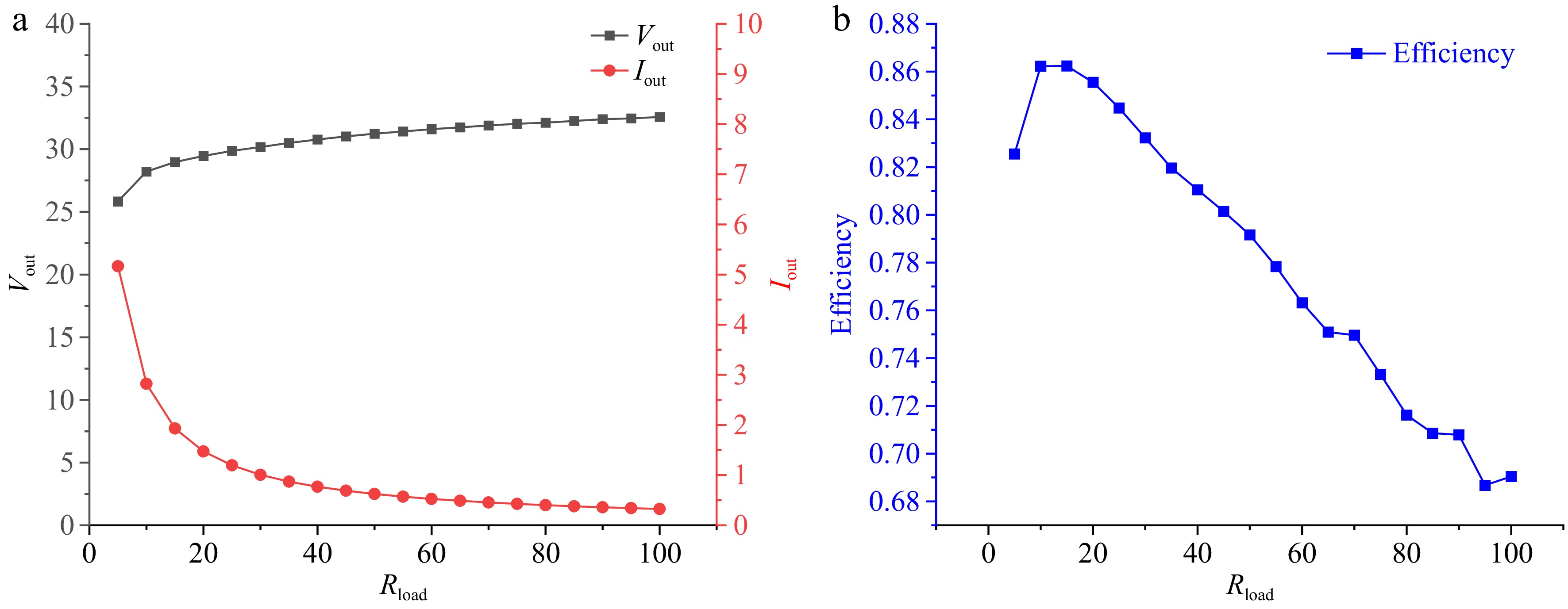
Figure 6.
(a) Experimental output voltage and output current, and (b) system efficiency.
In the present system, it is important to consider the operational behavior under extreme conditions such as short-circuit and open-circuit scenarios. When the system is under a short-circuit condition, the actual output power of the system increases. However, due to the load-independent design of the system, the primary side can still maintain Zero Voltage Switching (ZVS). This ensures that the voltage stress on the components does not increase significantly, and the resonance current peak of the transmitter coil reaches 12 A, with only a slight deviation from the stable operating current of 8 A. This behavior demonstrates the robustness of the system under short-circuit conditions, ensuring stable operation without causing undue stress on the system components.
Conversely, when the system is under open-circuit conditions, the inverter may operate in a non-ZVS state, which leads to an increase in primary-side losses. To enhance system stability in such scenarios, we propose the addition of a DC/DC converter at the output stage. This converter will act to limit the output voltage to the set value, thereby providing open-circuit protection and reducing potential system instability caused by non-ZVS operation.
While the system's load-independent design ensures that ZVS is maintained during short-circuit operation, there is still room for improvement in system performance under a range of load conditions. In the future, we plan to experimentally validate the multi-receiver prototype, focusing on optimizing system efficiency, ensuring stable voltage and power distribution, and achieving consistent voltage output under various load conditions. This will be critical for further enhancing the system's stability, particularly in practical applications involving multiple receivers and dynamic load variations.
-
This study successfully develops a high-frequency wireless power transfer (WPT) system featuring a load-independent Class EF inverter capable of achieving stable and efficient operation under varying load conditions. By employing a resonant circuit design and optimizing key parameters, the system delivers a constant voltage output with full zero-voltage switching (ZVS) over a wide range of operating scenarios, including low coupling coefficients. The experimental results validate the system's ability to maintain a constant output current of 8 A, achieve a peak efficiency of 84.6%, and handle dynamic load variations from 10 to 50 Ω without the need for manual tuning or component adjustments.
This research provides a robust and practical WPT solution, addressing critical limitations in conventional load-dependent systems. By maintaining zero-voltage switching (ZVS) operation even under significant coupling coefficient variations, the system ensures consistent performance across diverse operating scenarios. It demonstrates significant potential for applications requiring high flexibility, compact design, and stable performance, such as unmanned aerial vehicle (UAV) charging. In UAV applications, the system's ability to withstand coupling coefficient variations is particularly critical, as spatial misalignment during flight or landing can significantly impact energy transfer efficiency. The proposed design not only ensures reliable charging but also eliminates the need for frequent manual adjustments, making it ideal for dynamic-load systems like UAVs operating in complex and changing environments. The findings offer valuable insights for advancing the design of WPT systems toward broader real-world applicability.
This project received support from the Key Technology Project of State Grid Jiangsu Electric Power Co., Ltd. Research on Key Technologies of Perching Self-charging drone for Long-duration Power Line Inspection.gy (Grant No. J2023052).
-
The authors confirm contribution to the paper as follows: study conception and design: Wei Z, Wu Y, Chen Y; data collection: Wei Z, Zhao X, Zhang S; analysis and interpretation of results: Wei Z, Wu Y, draft manuscript preparation: Du X, Long T. All authors reviewed the results and approved the final version of the manuscript.
-
All data included in this study are available upon request by contact with the corresponding author.
-
The authors declare that they have no conflict of interest.
- Copyright: © 2025 by the author(s). Published by Maximum Academic Press, Fayetteville, GA. This article is an open access article distributed under Creative Commons Attribution License (CC BY 4.0), visit https://creativecommons.org/licenses/by/4.0/.
-
About this article
Cite this article
Wu Y, Chen Y, Zhao X, Zhang S, Du X, et al. 2025. Design and implementation of load-independent constant voltage output for medium-range 6.78 MHz wireless power transfer systems. Wireless Power Transfer 12: e016 doi: 10.48130/wpt-0025-0008 

Design and implementation of load-independent constant voltage output for medium-range 6.78 MHz wireless power transfer systems
- Received: 12 December 2024
- Revised: 23 January 2025
- Accepted: 14 February 2025
- Published online: 13 June 2025
Abstract: This paper presents a 6.78 MHz wireless power transfer (WPT) system designed to provide load-independent constant voltage output, making it ideal for applications such as unmanned aerial vehicle (UAV) charging. The system ensures stable voltage across a wide range of load variations while maintaining zero-voltage switching (ZVS) operation. Operating with a coupling coefficient k = 0.08 and a compact receiver coil measuring 6 cm × 3 cm on the secondary side, the system demonstrates high efficiency and compactness. Theoretical analysis establishes the conditions for achieving load-independent operation, which are validated through simulations and experimental results. The prototype achieves a stable output voltage and consistent ZVS performance under dynamic load conditions, addressing key challenges in WPT for UAVs and other applications with variable loads. Experimental testing of the prototype showed a measured efficiency of 80.4% at 66 W, confirming its practical feasibility.
-
Key words:
- Class EF /
- 6.78 MHz /
- Load-independent /
- CV