


-
Seawater Wireless Power Transfer (SWPT) systems are essential for powering underwater devices. They overcome the limitations of traditional power supply methods while enhancing flexibility and safety[1]. The current research focuses on coil structure design to enhance system transmission efficiency[2], reduce electromagnetic field leakage[3], improve anti-offset characteristics to counter irregular current interference[4], and address the challenge of simultaneous energy and information transmission in seawater[5].
Seawater's high electrical conductivity and dielectric constant introduce parasitic resistance and capacitance in a seawater environment. Parasitic resistance causes phase shifts between the primary and secondary coils, reducing transmission efficiency. Additionally, parasitic capacitance can interact with the coils to create resonance, potentially disrupting the system's intended resonance state[6,7].
Neglecting the effects of eddy current losses when designing SWPT systems can result in unpredictable reductions in system efficiency. To address this, Z-parameters can be used to effectively model the system, enabling accurate predictions of eddy current losses through a simplified circuit[8]. Eddy current losses cause phase changes between the primary and secondary coils. A compensating inductor can be added to the primary circuit to maintain consistent phase angles between these coils in seawater and air environments[9].
Additionally, eddy current losses lead to extra energy dissipation, which can be mitigated by modifying the system structure and lowering the operating frequency, thus improving efficiency and stability. A three-coil structure is proposed, which reduces eddy current losses by nearly half compared to traditional two-coil systems while increasing transmission efficiency by approximately 10%[10]. Eddy current losses rise significantly as the transmission distance and system frequency increase. Lowering the operating frequency in long-distance SWPT systems is advisable to ensure efficient and stable power transmission[11].
Previous papers on SWPT systems modeling typically consider the effects of conductivity by incorporating parasitic resistance into the circuit. However, few studies have accounted for the impact of the dielectric constant. A transmission method based on single capacitance coupling considers parasitic capacitance between coils and the ground. This approach significantly extends communication distance and enables full-duplex communication at 1 Mb/s without additional structures[12]. However, this approach, proposed for signal transmission, does not analyze the impact of parasitic capacitance caused by the dielectric constant. In the UWPT systems, a potential difference exists between the primary and secondary coils, thereby giving rise to distributed capacitance effects. Such capacitance impacts the topology structure of UWPT systems to a certain extent[13]. At low frequencies, the large reactance of the bridging capacitance acts as an open circuit, allowing the dielectric constant to be neglected. However, as frequency increases, this capacitance resonates with the coil inductance, impacting the system. Currently, there is no comprehensive equivalent model for SWPT that simultaneously considers the effects of both parasitic capacitance and parasitic resistance.
This paper presents the development of the SWPT system, proposing a dual-port model that accounts for stray capacitance and parasitic capacitance in seawater, along with an equivalent circuit model based on SS topology. This model more accurately reflects the actual conditions in seawater. After validating the model through finite element analysis, the system's resonant frequency was optimized based on this model. Finally, prototype experiments confirmed the correctness of the theoretical analysis.
-
The mutual inductance model traditionally used for air environments does not accurately capture the conditions in seawater. Seawater's high electrical conductivity results in additional energy losses, while its high dielectric constant significantly increases the inter-turn capacitance and stray capacitance between coils, creating much greater differences than air. Therefore, when modeling in a seawater environment, it is crucial to consider the effects of these capacitances and resistances to ensure the model's accuracy.
The traditional two-port WPT model is shown in Fig. 1a, where U1 and U2 represent the AC voltages of the inverter and rectifier, respectively. While I1 and I2 denote the system's input and output currents. L1 and L2 correspond to the self-inductances of the primary and secondary coils in air, and Mair represents the mutual inductance in air. RL1 and RL2 are the internal resistances of the primary and secondary coils. When the load resistance at the output is RL, the input impedance of the traditional WPT system is given by Wang et al.[14]:
$ {Z_{in}} = j\omega {L_1} + {R_{L1}} + \dfrac{{{\omega ^2}{M^2}}}{{j\omega {L_2} + {R_{L2}} + {R_L}}} $ (1) 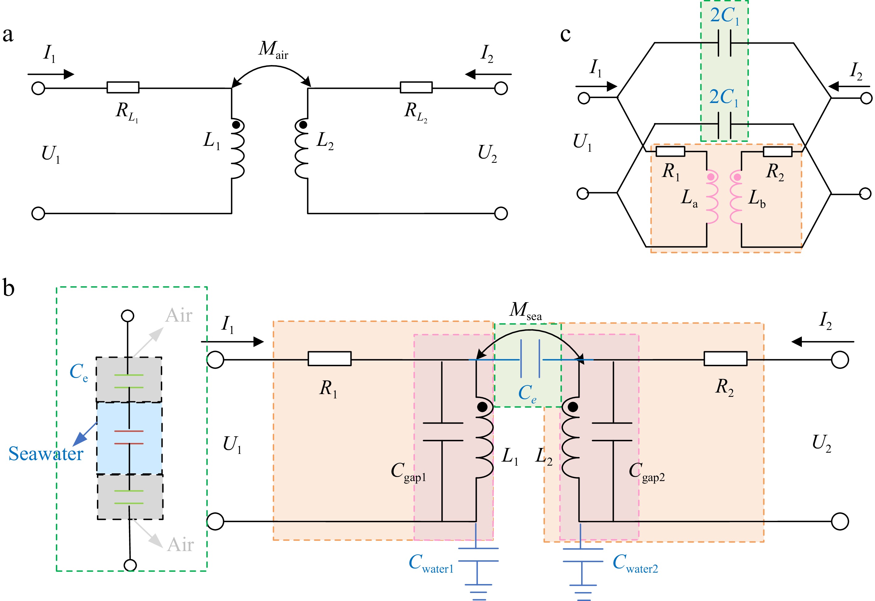
Figure 1.
Two-port models of WPT system. (a) Traditional mutual inductance model. (b) Model considering parasitic capacitance. (c) Simplified model considering parasitic capacitance.
The two-port model that considers parasitic capacitance is shown in Fig. 1b Compared to Fig. 1a, it includes the stray capacitance Ce between the two coils, where Ce is derived from the series combination of the air-water-air capacitances[15], as well as the capacitances Cwater1 and Cwater2 formed between the primary and secondary coils and seawater. At this point, the resistances R1 and R2 represent the sum of the internal coil resistances RL1 and RL2, and the eddy current loss resistances in seawater Reddy1 and Reddy2[16], where R1 = RL1 + Reddy1 and R2 = RL2 + Reddy2. The coils also have inter-turn capacitances Cgap1 and Cgap2. However, the model in Fig. 1b is overly complex, and some capacitances cannot be directly measured. Therefore, the model has been simplified, as shown in Fig. 1c. In this simplified model, the coil inductances La and Lb take into account the inter-turn capacitances of the coils, which can be directly measured using a digital bridge. La = L1 / (1 − ω2 L1Cgap1), Lb = L2 / (1 − ω2 L2Cgap2). The equivalent capacitance C1 is defined as the series combination of the stray capacitance and the capacitances to seawater, which is expressed as 1 / (1/ Ce + 1/Cwater1 + 1/Cwater2), and to simplify further calculations, C1 is split into two parallel capacitors of 2C1. C1, obtained through direct measurement using a digital bridge, fully reflects the temperature characteristics and salinity effects in the actual environment. The proposed model demonstrates excellent adaptability under both low-temperature and high-salinity conditions.
The impedance model for a pure mutual inductance network in seawater is:
$ {{\mathbf{{\rm Z}}}_{water}} = \left[ {\begin{array}{*{20}{c}} {j\omega {L_a}}&{j\omega M} \\ {j\omega M}&{j\omega {L_b}} \end{array}} \right] $ (2) Convert impedance matrix to admittance matrix Ywater:
$ {{\mathbf{Y}}_{water}} = \left[ {\begin{array}{*{20}{c}} {\dfrac{{ - j{L_b}}}{{({L_a}{L_b} - {M^2})\omega }}}&{\dfrac{{jM}}{{({L_a}{L_b} - {M^2})\omega }}} \\ {\dfrac{{jM}}{{({L_a}{L_b} - {M^2})\omega }}}&{\dfrac{{ - j{L_a}}}{{({L_a}{L_b} - {M^2})\omega }}} \end{array}} \right] $ (3) The admittance matrix for the equivalent capacitance network is:
$ {{\mathbf{Y}}_C} = \left[ {\begin{array}{*{20}{c}} {j\omega {C_1}}&{ - j\omega {C_1}} \\ { - j\omega {C_1}}&{j\omega {C_1}} \end{array}} \right] $ (4) Overlay Eqns (3) and (4):
$ {\mathbf{Y}} = {{\mathbf{Y}}_{water}} + {{\mathbf{Y}}_c} $ (5) Convert Eqn (5) into a transmission matrix T:
$ {\mathbf{T}} = \left[ {\begin{array}{*{20}{c}} {\dfrac{{( - {L_a}{L_b} + {M^2}){C_1}{\omega ^2} + {L_a}}}{{( - {L_a}{L_b} + {M^2}){C_1}{\omega ^2} + M}}}&{ - \dfrac{1}{{\dfrac{{jM}}{{\omega ({L_a}{L_b} - {M^2})}} - j\omega {C_1}}}} \\ {\dfrac{{j( - 1 - 2(M - \dfrac{{{L_a}}}{2} - \dfrac{{{L_b}}}{2}){C_1}{\omega ^2})}}{{(( - {L_a}{L_b} + {M^2}){C_1}{\omega ^2} + M)\omega }}}&{\dfrac{{( - {L_a}{L_b} + {M^2}){C_1}{\omega ^2} + {L_b}}}{{( - {L_a}{L_b} + {M^2}){C_1}{\omega ^2} + M}}} \end{array}} \right] $ (6) Write the transmission matrix Ta, Tb for the internal resistance R1 and R2 columns of the primary and secondary coils:
$ {{\mathbf{T}}_a} = \left[ {\begin{array}{*{20}{c}} 1&{{R_1}} \\ 0&1 \end{array}} \right],{{\mathbf{T}}_b} = \left[ {\begin{array}{*{20}{c}} 1&{{R_2}} \\ 0&1 \end{array}} \right] $ (7) Regarding the transmission matrix T, Ta and Tb are cascaded:
$ \begin{split}& {{{\mathbf{T}}_{in1}} = {{\mathbf{T}}_a}{\mathbf{T}}{{\mathbf{T}}_b} =} \\& \left[ \begin{aligned} &{{\dfrac{{A\omega - 2j{R_1}B{\omega ^2} + {L_a}\omega - j{R_1}}}{{(A + M)\omega }}}} && {{\dfrac{{A({R_1} + {R_2})\omega + j( - 2{R_1}B{R_2} - {M^2} + {L_a}{L_b}){\omega ^2} + ({L_a}{R_2} + {L_b}{R_1})\omega - j{R_1}{R_2}}}{{(A + M)\omega }}}} & \\ & {{\dfrac{{j( - 1 - 2B{\omega ^2})}}{{(A + M)\omega }}}} && {{\dfrac{{{C_1}A\omega - 2j{R_2}B{\omega ^2} + {L_b}\omega - j{R_2}}}{{(A + M)\omega }}}} & \end{aligned} \right] \\ \end{split} $ (8) where, A = (− La Lb + M2) C1 ω2, B = (M − La / 2 − Lb / 2) C1.
The output load resistance is set to RL and U2 = −I2RL, the input impedance in Zin1 is:
$ \begin{split}& {Z_{in1}} = - \dfrac{{{{\mathbf{T}}_{in1}}[1,1]{R_L} + {{\mathbf{T}}_{in1}}[1,2]}}{{{{\mathbf{T}}_{in1}}[2,1]{R_L} + {{\mathbf{T}}_{in1}}[2,2]}}= \\ & {\dfrac{{ - jA\omega ({R_1} + {R_2} + {R_L}) + ( - 2{R_1}({R_2} + {R_L})B - {M^2} + {L_a}{L_b}){\omega ^2} - j({L_b}{R_1} + {L_a}({R_2} + {R_L}))\omega - {R_1}({R_2} + {R_L})}}{{j\omega A + 2({R_2} + {R_L})B{\omega ^2} + j\omega {L_b} + {R_2} + {R_L}}}} \\ \end{split} $ (9) Modeling of SWPT with S-S topology
-
The circuit should add compensation capacitors to improve the system's transmission capacity and power factor. This paper chooses the SS topology with a simple structure and good load adaptability[17]. As shown in Fig. 2, Ca and Cb are the compensation capacitors for the primary and secondary sides, R1 = Reddy1 + RL1, and R2 = Reddy2 + RL2.
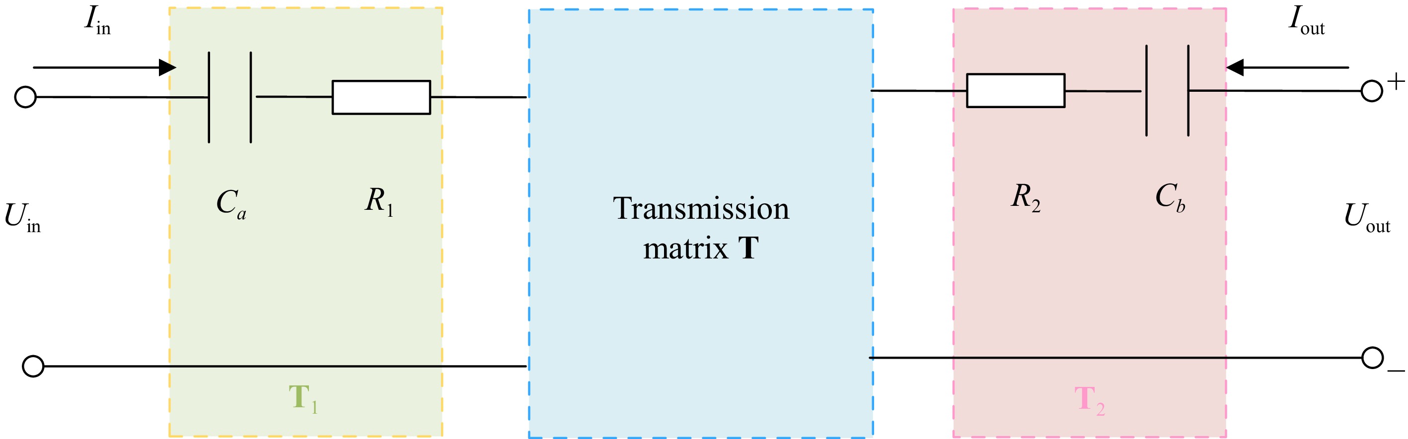
Figure 2.
Modeling of SWPT with S-S topology.
The transmission matrix T is shown in Eqn (6), Write the transmission matrices T1 and T2 for the original secondary edge compensation network column.
$ {{\mathbf{T}}_1} = \left[ {\begin{array}{*{20}{c}} 1&{{R_1} + 1/j\omega {C_a}} \\ 0&1 \end{array}} \right],{{\mathbf{T}}_2} = \left[ {\begin{array}{*{20}{c}} 1&{{R_2} + 1/j\omega {C_b}} \\ 0&1 \end{array}} \right] $ (10) Cascade T, T1, T2:
$ {{\mathbf{T}}_{in2}} = {{\mathbf{T}}_1}{\mathbf{T}}{{\mathbf{T}}_2} $ (11) The input impedance of this model can be expressed as:
$ Z_{in2}=\frac{\mathbf{T}_{in2}(1,1)R_{_L}+\mathbf{T}_{in2}(1,2)}{\mathbf{T}_{in2}(2,1)R_{_L}+\mathbf{T}_{in2}(1,2)} $ (12) When the imaginary part of the input impedance reaches zero, the system achieves a zero-phase angle (ZPA), further improving its efficiency. At this point, considering the stray capacitance, the system's resonant frequency can also be derived. By substituting the various parameters of the system into this equation, the actual operating frequency of the SWPT system considering parasitic capacitance can be obtained:
$ - 4 - a{\omega ^8} - b{\omega ^6} - c{\omega ^4} - d{\omega ^2} = 0 $ (13) where, the expanded formulas for a, b, c, and d are as follows:
$ \left\{\begin{aligned}a= & ((C_aR_2^2-2C_aR_2R_L+C_aR_L^2-L_b)L_a+C_a(-R_L+R_2)^2L_b \\ & \; \; +(M-2C_a(-R_L+R_2)^2)M)C_b+C_a(-L_aL_b+M^2))C_1 \\ & \; \; +2(-L_aL_b+M^2)C_aC_b)C_b(-L_aL_b+M^2)C_1 \\ b= & 2(-2(-R_L+R_2)^2(M-L_a/2-L_b/2)C_b^2+(-2L_aL_b+2M^2)C_b \\ & \; \; +C_a(-L_aL_b+M^2))(M-L_a/2-L_b/2)C_1^2 \\ & \; \; +4C_b((-C_a(-R_L+R_2)^2L_a^2/2+(L_b^2-C_a(-R_L+R_2)^2L_b \\ & \; \; +MC_a(-R_L+R_2)^2)L_a+((-2L_b+C_a(-R_L+R_2)^2)M^2)/2)C_b \\ & \; \; +C_a(M-L_a-L_b)(-L_aL_b+M^2))C_1-4C_aC_b^2L_b(-L_aL_b+M^2) \\ c= & -4(M-L_a/2-L_b/2)^2C_1^2+(-8(-R_L+R_2)^2(M-L_a/2-L_b/2)C_b^2 \\ & \; \; +(-8L_aL_b-4L_b^2+8L_bM+4M^2)C_b+2C_a(-L_a^2+(2M-2L_b)L_a \\ & \; \; +M^2))C_1+4C_b((C_a(-R_L+R_2)^2L_a-L_b^2)C_b+C_a(-2L_aL_b+M^2)) \\ d= & -(-8M+4L_a+4L_b)C_1-4(-R_L+R_2)^2C_b^2+8C_bL_b+4C_aL_a \end{aligned}\right. $ (14) This paper focuses on the SS topology, deriving the SWPT system's actual operating frequency while accounting for parasitic capacitance effects. The proposed methodology is equally applicable to other compensation topologies, with the primary distinction being the variation in the transmission matrix Tin.
-
An SWPT model was developed to verify the impact of stray capacitance on the SWPT system, and the system parameters are shown in Table 1. A low frequency and a high frequency were selected to verify the impact of stray capacitance on the SWPT system. The measured inductance values La and Lb differ significantly at 100 and 700 kHz because, at high frequencies, the interaction between distributed capacitance and inductance leads to a notable increase in the equivalent capacitance value.
Table 1. System parameters.
Note Symbol Value Primary/secondary inductance La/Lb 100 k 233.2 μH / 229.5 μH 700 k 490.5 μH / 461 μH Coupling coefficient kps 100 k 0.0443 700 k 0.0449 Resonant capacitor Ca/Cb 100 k 5.5 nF / 5.16 nF 700 k 112 pF / 105 pF Litz wire standard 0.1 × 550 Litz wire diameter 4 mm Number of turns N1/N2 14 Coil diameter d1 200 mm Seawater region 500 mm × 270 mm × 300 mm Gap d 100 mm Operating frequency f 100 kHz / 700 kHz Conductivity of seawater σ 4 S/m Influence of parasitic capacitance
-
First, the inter-turn capacitance and the stray capacitance sizes were studied. The inter-turn capacitance Cgap and the stray capacitance C1 between the coils was measured using a vector network analyzer and a digital bridge. As shown in Fig. 3a, the variation of the inter-turn capacitance with different numbers of turns was analyzed in both air and seawater environments. Although the coils were placed inside an air shell, the entire setup was submerged in seawater, resulting in slightly higher inter-turn capacitance in seawater than in air. Despite some fluctuations in the curve due to measurement noise, the inter-turn capacitance increased with the number of turns in both seawater and air. As depicted in Fig. 3b, the stray capacitance C1 in air rapidly decreased as the distance between the coils increased, whereas, in seawater, C1 remained nearly constant with increasing distance. It is worth noting that when the coil undergoes lateral displacement, the stray capacitance value remains relatively stable and does not show significant displacement distance dependence. Moreover, C1 increased significantly with the number of turns in both air and seawater.
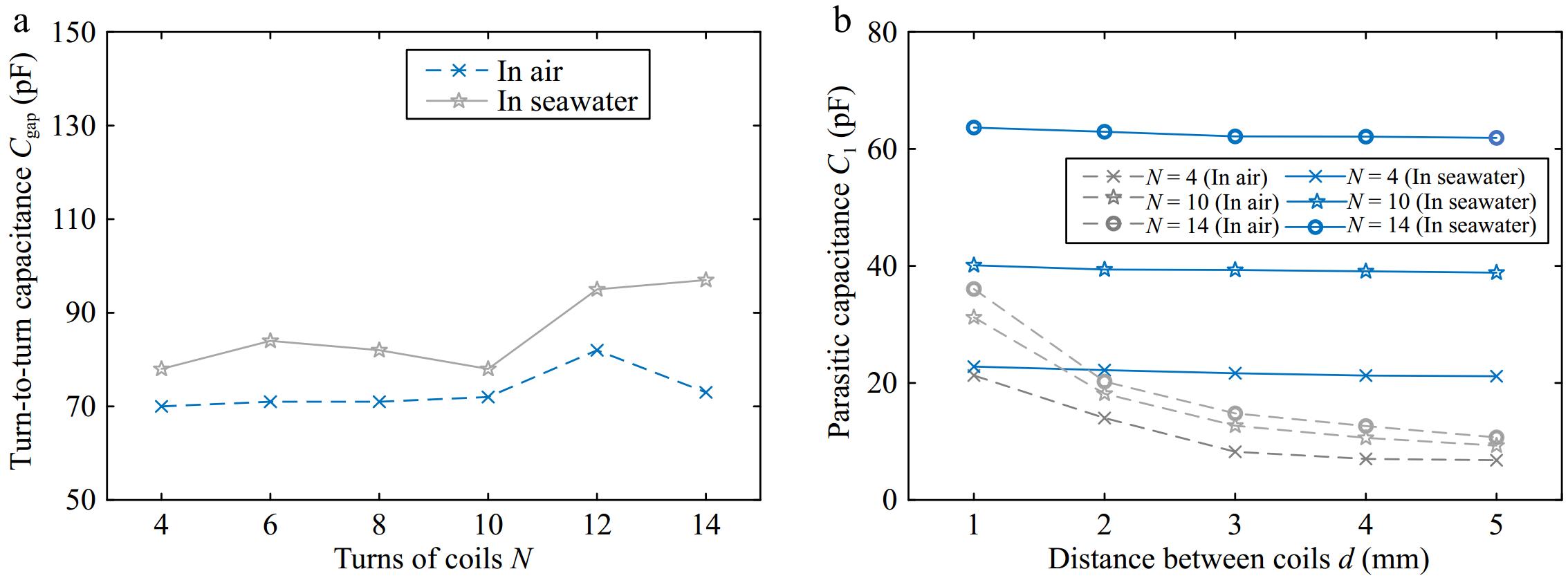
Figure 3.
Measurement results in air and seawater. (a) Using a vector analyzer to measure Cgap as a function of turns N. (b) Using a digital bridge to measure C1 as a function of distance d between coils.
Using the capacitance values measured in Fig. 3, we analyzed the input impedance variations for a pure mutual inductance model and a model that includes inter-turn and stray capacitances in air and seawater. As shown in Fig. 4a, the three curves overlap at low frequencies, indicating a minimal capacitance effect, and the traditional mutual inductance model accurately captures the system's characteristics. However, as the frequency increases, the effect of capacitance becomes more pronounced, leading to resonance with the coil and causing rapid fluctuations in the input impedance magnitude. In seawater, the input impedance is affected at lower frequencies, while in air, the capacitance impact occurs at higher frequencies. Therefore, in air, the effect of capacitance can be ignored, allowing the use of the traditional mutual inductance model. In contrast, after selecting the operating frequency in seawater, the capacitance must be measured to determine its impact and whether a more precise model incorporating capacitance is necessary.
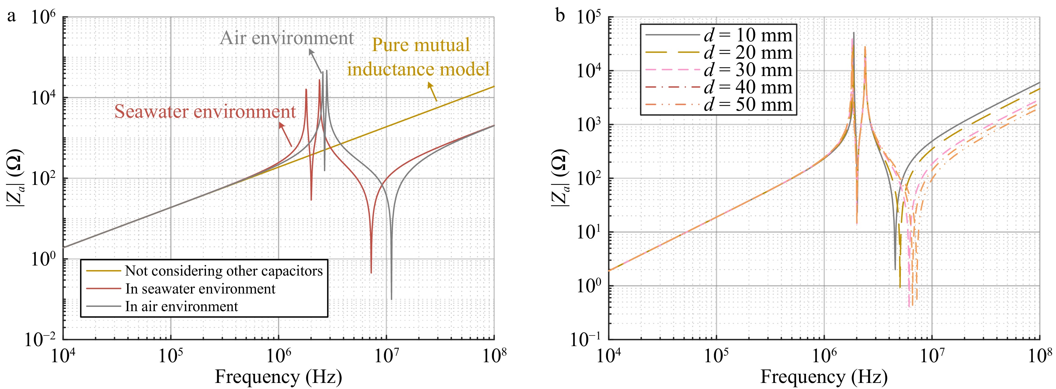
Figure 4.
Calculation results. (a) Frequency characteristics of impedance amplitude. (b) Frequency characteristics of impedance amplitude of distance d between coils.
We also analyzed the frequency response of the input impedance magnitude at different distances, as shown in Fig. 4b. The curves show minimal variation, indicating that the frequency points where input impedance changes remain largely constant despite distance variations. This implies that adjusting the distance between coils does not effectively reduce the impact of stray capacitance in a seawater environment.
Optimization of resonant frequency
-
To verify the impact of stray capacitance on the SWPT system, we performed simulation analysis in LT-spice at both a lower frequency and a higher frequency.
After determining the coil structure, the capacitance at 100 kHz can be calculated using the resonance frequency formula for the SS topology[18]. By substituting the parameters from Table 1 into Eqn (13), it is confirmed that the resonance frequency remains 100 kHz in a seawater environment. Based on the parameters from Table 1, a simulation analysis is then conducted.
With the input voltage set to 100 V, as shown in Fig. 5a, the system reaches resonance at 100 kHz. The resonance condition remains unchanged after introducing stray capacitance into the system, as depicted in Fig. 5b. This demonstrates that the stray capacitance does not affect the system's resonance at low frequencies. The simulation results are in close agreement with the calculated values.
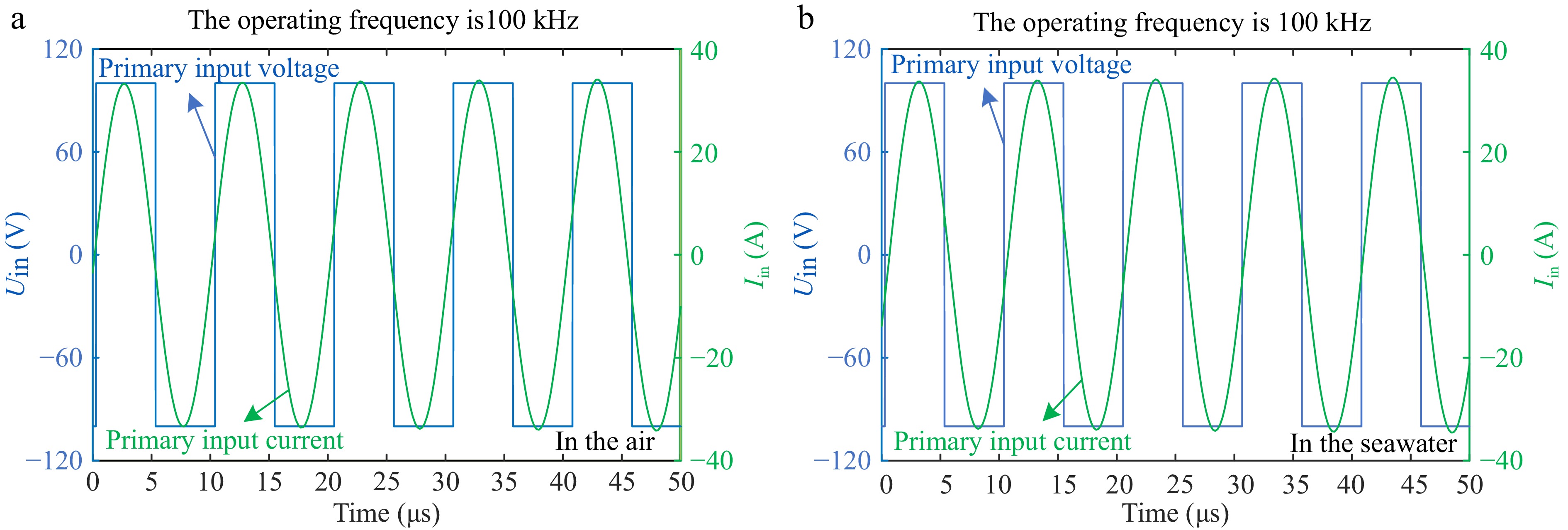
Figure 5.
Low-frequency simulation waveform. (a) In the air. (b) In the seawater.
The system's resonant frequency in air is adjusted to 700 kHz, and the corresponding resonant capacitance is calculated. By substituting the parameters into Eqn (13), the resonant frequency in seawater is determined to be 689 kHz.
In Fig. 6a, the system in the air reaches resonance at 700 kHz. After introducing stray capacitance into the circuit, as shown in Fig. 6b, the system deviates significantly from resonance, and the current value also changes. To restore resonance, the operating frequency must be adjusted. As depicted in the Fig. 6c, the system regains resonance at 683 kHz. The simulated and calculated values are consistent. Thus, at higher frequencies, the capacitance caused by the dielectric constant significantly affects the system's resonant frequency.
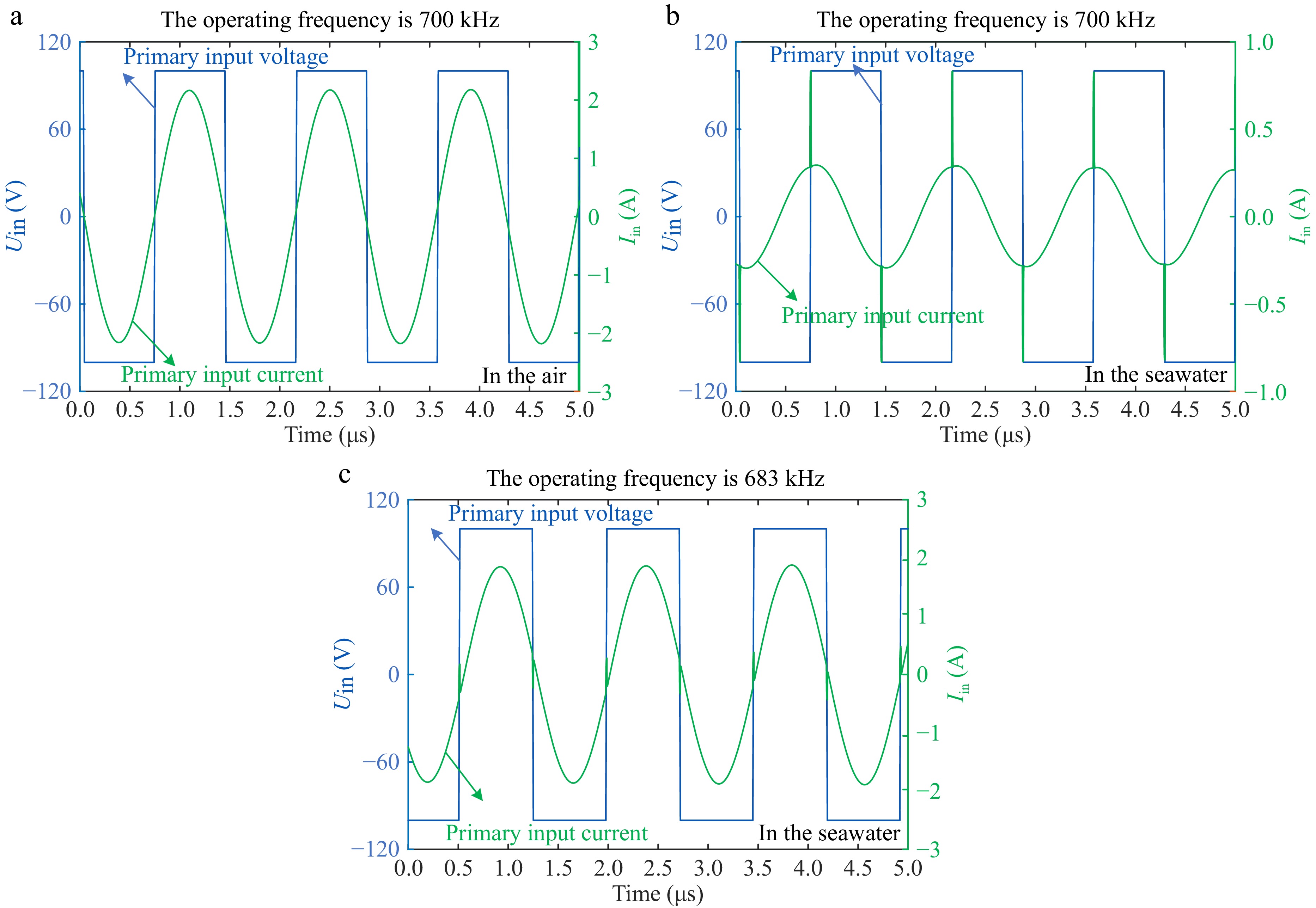
Figure 6.
High-frequency simulation waveform. (a) In the air. (b) In the seawater. (c) Readjust back to the resonance state.
Experimentation result
-
To validate the theoretical analysis, a seawater experimental prototype was developed, as shown in Fig. 7. The transmitter and receiver coils consist of three layers of flat square spiral coils, with a 4 mm radius Litz wire wound in 14 turns. The Litz wire comprises 550 strands of 0.1 mm diameter enameled wire. AC power modulation is achieved using a wide-bandgap silicon carbide (SiC) MOSFET (IMZ120R045M1) and a SiC diode (IDW40G120C5B). The conductivity of the seawater is adjusted to 4 S/m.
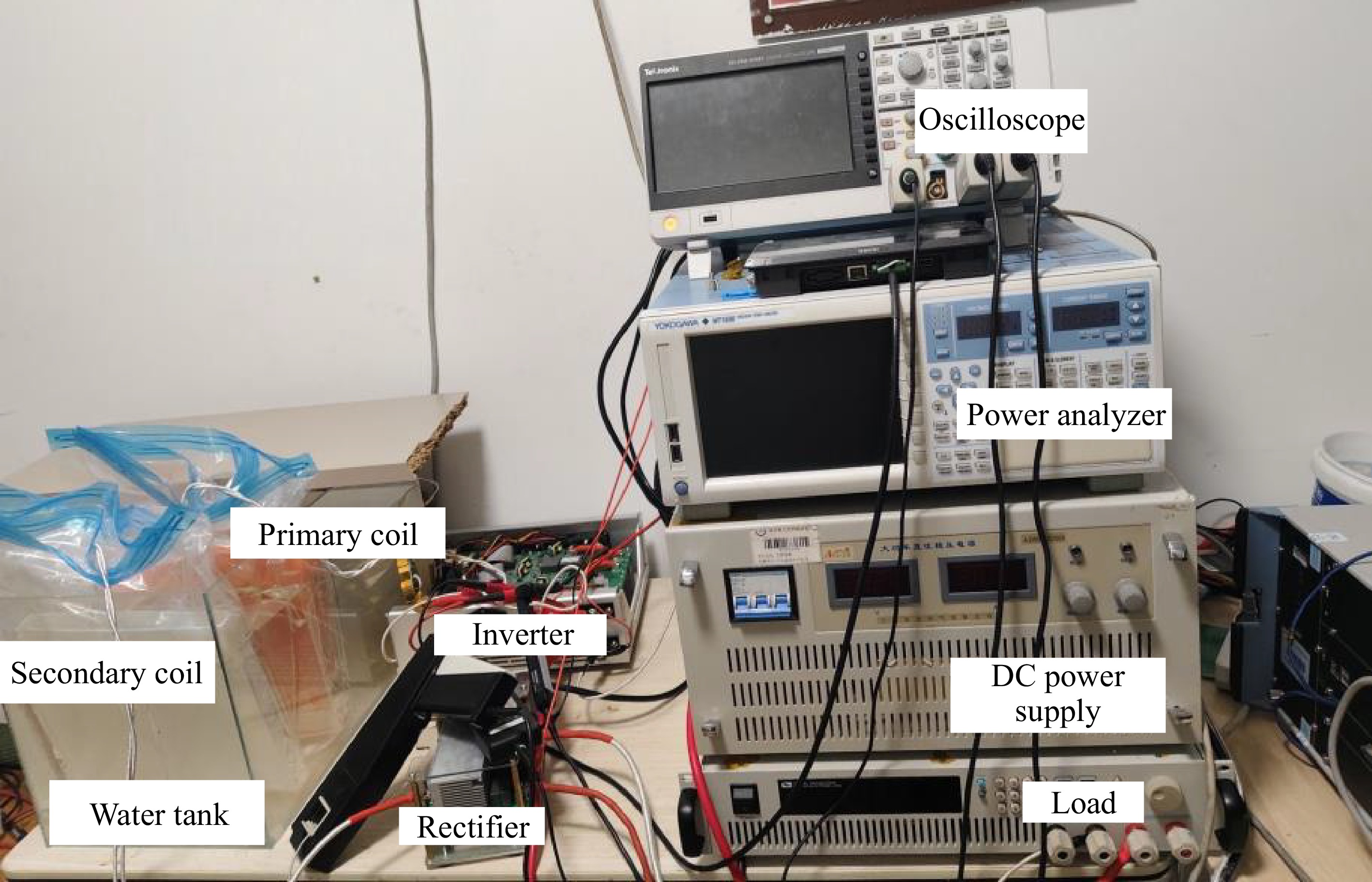
Figure 7.
The experimental setup for SWPT system.
In the low-frequency air environment, the system achieved stable resonance at the theoretical resonant frequency of 100 kHz, with the measured results fully consistent with the calculated values, as shown in Fig. 8a. After immersing the device in seawater as shown in the Fig. 8b, despite the introduction of stray capacitance from the seawater medium, the resonant frequency remained at 100 kHz without significant deviation. The experimental results indicate that in low-frequency conditions, the influence of stray capacitance on the resonant frequency can be neglected.
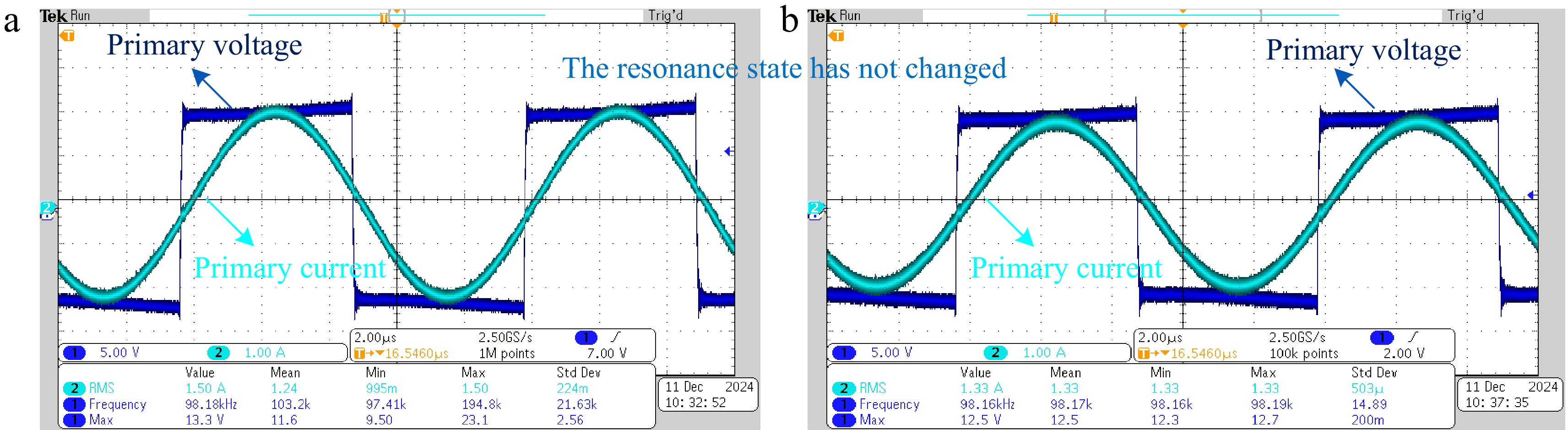
Figure 8.
Experimental waveforms for the SWPT system. (a) In the air. (b) In the seawater.
Figure 9a illustrates the transmission efficiency and power of the system at a frequency of 100 kHz in both air and seawater environments. Due to the higher conductivity of seawater, eddy current losses are generated in the system, resulting in slightly lower transmission efficiency in seawater compared to that in air. Figure 9b further compares the transmission efficiency and power in air at 700 kHz, seawater at 700 kHz, and seawater at 688 kHz. At high frequencies, the influence of stray capacitance causes a shift in the system's resonant state, leading to significantly lower transmission efficiency and power at 700 kHz compared to that at 688 kHz. By adjusting the resonant frequency to 688 kHz, the system can still achieve a resonant state and maintain normal power transmission, although its efficiency is slightly lower than that in air. Additionally, factors such as increased coil resistance at high frequencies also contribute to a slight decrease in transmission efficiency in air at 700 kHz.
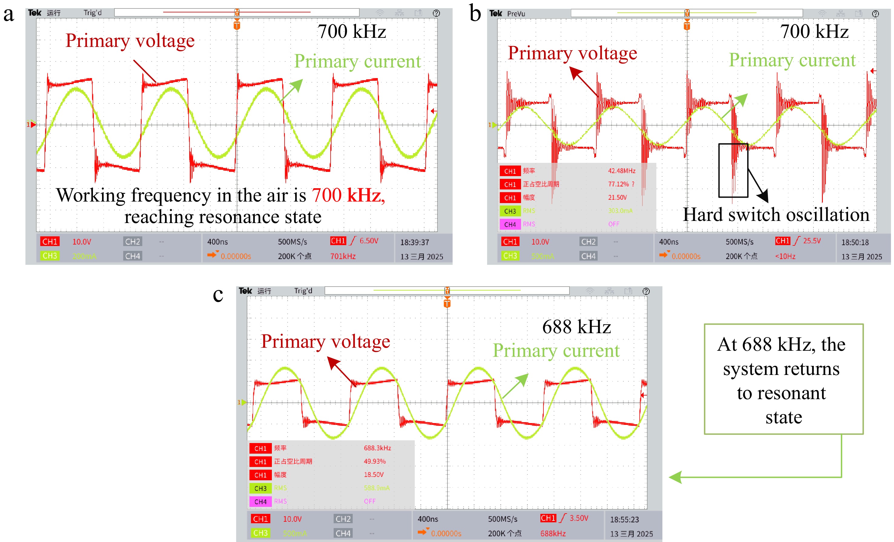
Figure 9.
Experimental waveforms for SWPT system. (a) In the air. (b) In the seawater. (c) Readjust back to resonance state.
Figure 10a illustrates the transmission efficiency and power of the system in both air and seawater environments at a frequency of 100 kHz. Due to the higher conductivity of seawater, eddy current losses are induced in the system, resulting in a slightly lower transmission efficiency in seawater compared to that in air. Figure 10b compares the transmission efficiency and power in air at 700 kHz with those in seawater at 688 kHz. At high frequencies, the influence of stray capacitance causes a shift in the system's resonant state. Therefore, by adjusting the resonant frequency to 689 kHz, the system can still achieve a resonant state and maintain normal power transmission. However, the efficiency is slightly lower than that in air. Additionally, factors such as increased coil resistance at high frequencies lead to a slight decrease in transmission efficiency in air at 700 kHz.
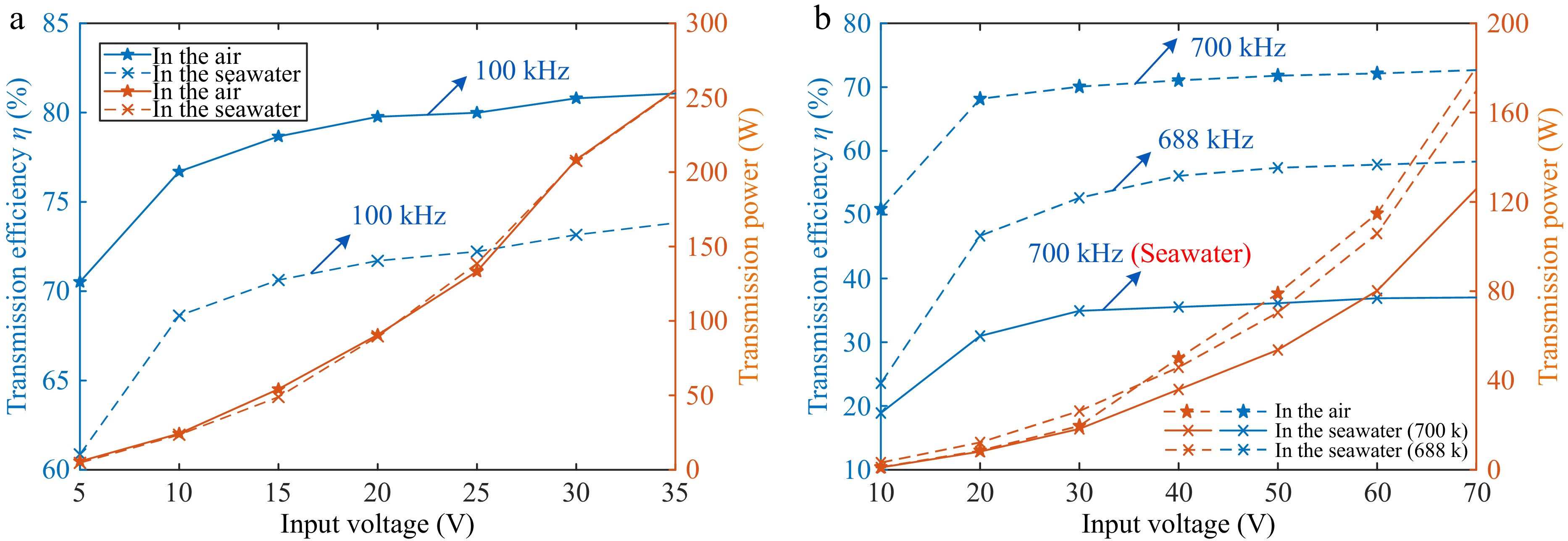
Figure 10.
System efficiency and transmission power. (a) Low frequency. (b) High frequency.
To more clearly present the experimental results, we have organized the key data in Table 2, facilitating an intuitive comparison of the changes in the system's resonant frequency.
Table 2. Experimental results.
System operating frequency 100 kHz 700 kHz Air Calculate 100 kHz 700 kHz Simulation 100 kHz 700 kHz Experiment 100 kHz 700 kHz Seawater Calculate 100 kHz 689 kHz Simulation 100 kHz 683 kHz Experiment 100 kHz 688 kHz Transmission efficiency Air 81.065% 72.667% Seawater 73.82% (100 kHz) 37.02% (700 kHz) Efficiency after adjusting frequency / 58.313% (688 kHz) Efficiency improvement points / 21.0293% It is recommended that the model proposed in this paper be adopted for system design for the requirements of high-frequency application scenarios. By considering the distribution of parasitic parameters under actual operating conditions, this model effectively enhances the computational accuracy of resonant networks and improves system stability, whose operational feasibility has been experimentally verified.
-
This paper presents the modeling and analysis of eddy current losses, stray capacitance due to high dielectric constants, and inter-turn capacitance in an SWPT system. The input impedance expression is derived using a two-port network model in seawater, accounting for inter-turn and bridging capacitances at any frequency. Impedance characteristics across different frequencies are analyzed for a pure mutual inductance model and one considering stray capacitance in air and seawater. Based on the equivalent model under the SS topology, the system's resonant frequency is derived with the inclusion of stray capacitance. The results demonstrate that, in a high-frequency seawater environment, the traditional pure mutual inductance model fails to represent the system's actual behavior accurately. By incorporating the effects of stray capacitance, the system's resonant frequency can be properly corrected.
The authors would like to thank the Kunming Branch of the 705 Research Institute for their internal project funding and support throughout this research.
-
The authors confirm contribution to the paper as follows: conceptualization: Yuan C, Wang F; methodology, writing—original draft preparation: Yu S; formal analysis: Yu S, Li H; data curation: Yu B; funding acquisition, writing—review and editing: Wang F; validation: Yu S, Yu B, Yuan C; project administration: Yuan C. All authors have read and agreed to the published version of the manuscript.
-
The data presented in this study are available on request from the corresponding author due to the funder's privacy policy.
-
The authors declare that they have no conflict of interest.
- Copyright: © 2025 by the author(s). Published by Maximum Academic Press, Fayetteville, GA. This article is an open access article distributed under Creative Commons Attribution License (CC BY 4.0), visit https://creativecommons.org/licenses/by/4.0/.
-
About this article
Cite this article
Yu S, Li H, Yu B, Yuan C, Wang F. 2025. Construction and analysis of precise circuit model for SWPT considering parasitic capacitance. Wireless Power Transfer 12: e018 doi: 10.48130/wpt-0025-0012 

Construction and analysis of precise circuit model for SWPT considering parasitic capacitance
- Received: 03 January 2025
- Revised: 11 April 2025
- Accepted: 24 April 2025
- Published online: 02 July 2025
Abstract: Due to seawater's high conductivity and dielectric constant, the traditional pure inductance model used in air cannot accurately describe the coil model in seawater wireless power transfer (SWPT). Therefore, this paper proposes a two-port model for SWPT in seawater, considering the inter-turn capacitance and stray capacitance induced by dielectric properties. The input impedance magnitude of the pure inductance model and the model considering inter-turn and stray capacitance in both air and seawater were analyzed to demonstrate the influence of the dielectric constant on the system's operating frequency. A system model based on the SS topology was established, and the system's resonant frequency was analyzed. Due to the dielectric constant influence, the SWPT system's actual frequency shifts, with higher system frequencies being more significantly affected. Therefore, when designing high-frequency SWPT systems, seawater's high dielectric constant and conductivity must be considered to achieve optimal operating frequency and maximum transmission efficiency. An SWPT prototype was developed, and experimental results confirmed the theoretical analysis.