

-
Wireless power transfer (WPT) represents a cutting-edge technology that has garnered a major focus of scientific inquiry. There are various energy carriers that are utilized to enable indirect power transmission between source and load, facilitating complete electrical isolation. Security, reliability, and adaptability are notable advantages of WPT. Conductor exposure hazards and interface wear mechanisms are systematically addressed by these intrinsic technical merits. The origins of WPT research can be traced back to the mid-19th century. However, technological limitations of the era hindered significant progress[1]. It was not until the 1980s that research in this field regained momentum, driven by the contributions of numerous research teams[2,3].
Figure 1 presents the classification of WPT. Based on transmission media, WPT can be categorized into two distinct domains: electromagnetic and mechanical wave-based WPT. Electromagnetic wave-based WPT can be further classified based on the wavelength of propagation into near-field coupled WPT (operating within one wavelength), and far-field coupled WPT (operating beyond one wavelength)[4]. Far-field coupled WPT includes technologies like microwave wireless power transfer (MWPT)[5], and optical wireless power transfer (OWPT)[6]. In contrast, near-field coupled WPT, which constitutes the majority of current research, is divided into capacitive power transfer (CPT), and inductive power transfer (IPT).
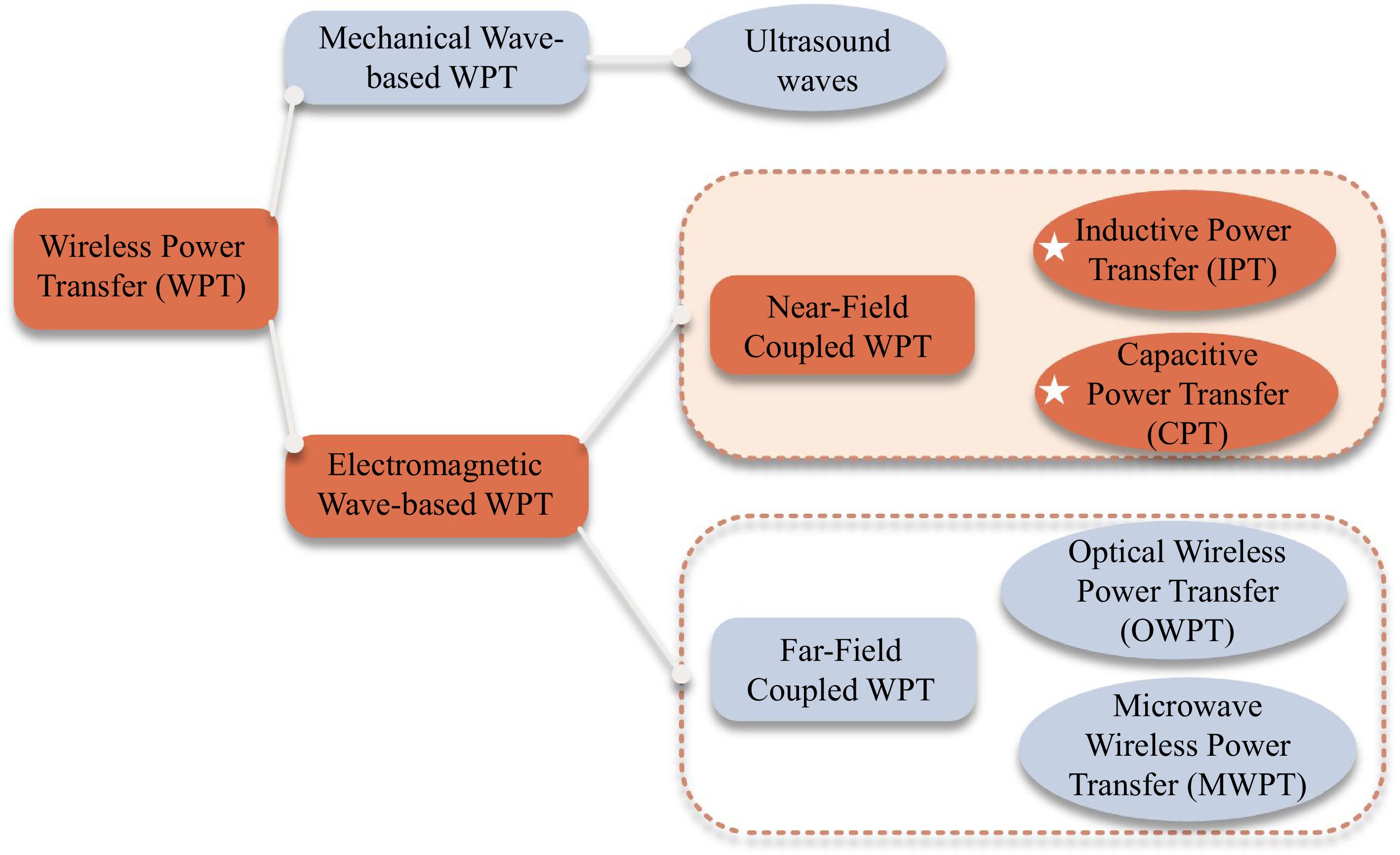
Figure 1.
Classification of WPT.
Distinct transmission channel configurations are identified as the source of WPT difference, being functionally decomposed into coupling mechanism variations and compensation topology designs. The structure and transmission performance of these components are determined by their specific designs. This integral structure and operational principle of the system are illustrated in Fig. 2. This paper systematically summarizes the characteristics of different transmission channels in IPT and CPT. However, the limitations of single-mode WPT technologies have manifested with increasing clarity, particularly as the field advances toward a future of high-power density and high distance-to-diameter. In this paper, we are concerned with the design of power transmission channels for hybrid wireless power transfer (HWPT) systems, which are a combination of IPT and CPT technologies. By leveraging the strengths of diverse transmission channels, HWPT is optimized to enhance overall performance, providing a more flexible and efficient solution for WPT.
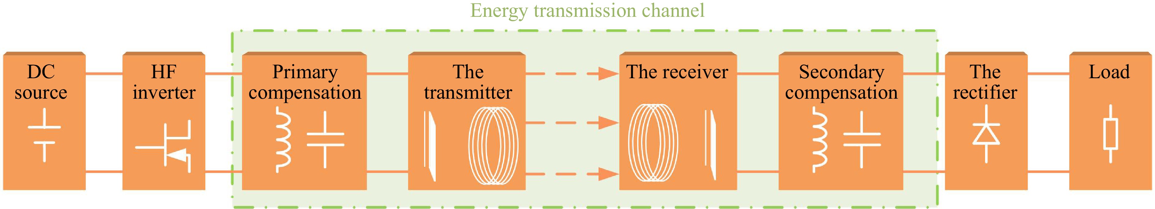
Figure 2.
Integral structure of the WPT system.
-
Based on the principle of electromagnetic induction, IPT systems employ magnetically coupling resonant coils to mediate power transfer through a high-frequency alternating magnetic field. In contrast to tightly coupled transformers, an IPT system can be regarded as a loosely coupled resonator with a large leakage inductance[7,8]. Coupling coils act as the core component of the transmission channel, enabling energy transfer through magnetic coupling, however, their inherent parasitic resistance degrades efficiency. To optimize power transfer capability, resonant compensation topology is used in engineering.
Structure of the coupling coils
-
As illustrated in Fig. 3, three basic configurations have been developed with distinct characteristics: (a) the basic two-coil structure[9], optimized for high-power transfer within short distances, features minimal component count. This structure is efficient in a short distance, yet its performance will decline rapidly with the increase of the distance-to-diameter; (b) the three-coil structure[10] adds a relay coil between two-coils, extending effective transmission range through a magnetic field superposition. However, it reduced power density in near-field applications; (c) the four-coil structure[11] can achieve maximum transmission distance through multi-stage relay coils, but the structural complexity and material costs are increased.
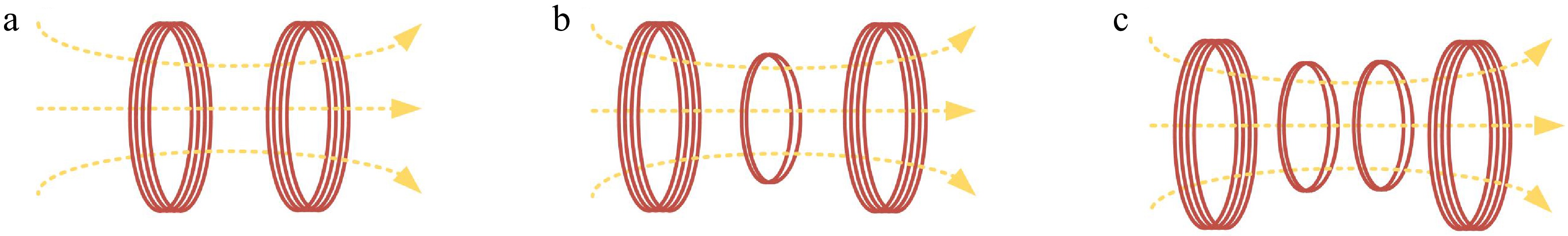
Figure 3.
Basic structures in the IPT system. (a) Two-coil. (b) Three-coil. (c) Four-coil.
The ongoing popularization and application of IPT are fostering substantial innovations in coupling coil. To address practical challenges in IPT, particularly efficiency degradation under misalignment, researchers have developed enhanced coil configurations building on three foundational coils. As presented in Fig. 4, the optimization of magnetic field distribution by designing the coil structure has resulted in the achievement of misalignment tolerance and an enhancement of transmission power[12−17]. These coupled coils are engineered for vehicular wireless power transfer systems, utilizing directional coupling mechanisms.
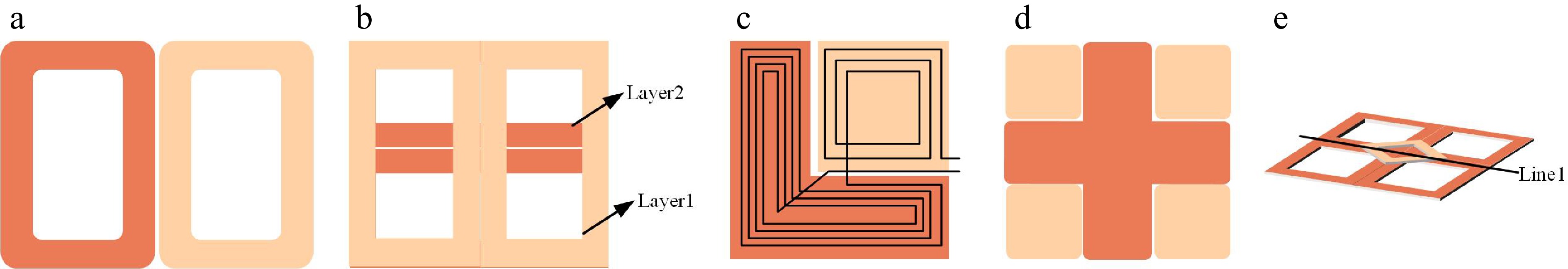
Figure 4.
Enhancing misalignment tolerance structures. (a) DD coil. (b) Double-layer DD coil. (c) LD coil. (d) Meter-type coil. (e) QDS coil.
The coils described above are primarily utilized for directional WPT applications. However, directional power transmission mode is usually limited to two-dimensional space and single reception, and the spatial flexibility is greatly restricted. To improve magnetic field power transmission with multi-degree-of-freedom in three-dimensional (3D) space, an in-depth analysis into the design of omnidirectional coils has been conducted. Figure 5 shows two different omnidirectional structures[18−20]. These coils are shedding new light on the control of magnetic field distribution and spatial degree of freedom.
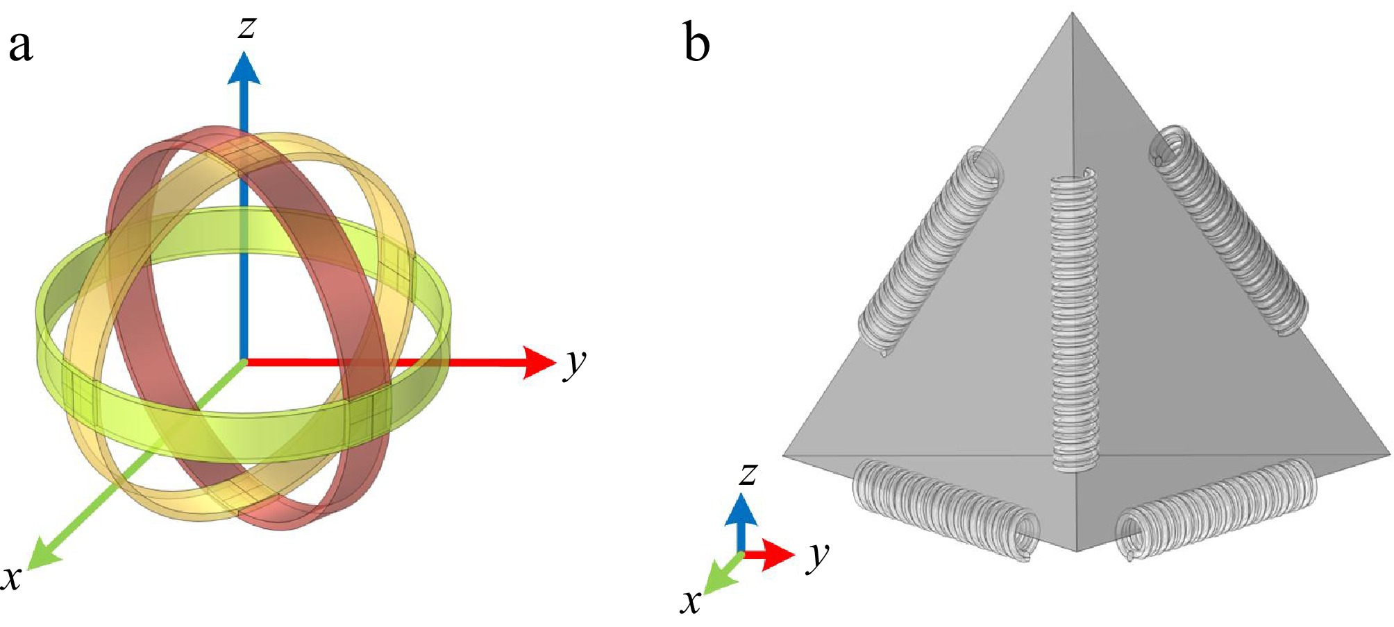
Figure 5.
Omnidirectional coupling coil structures. (a) Spherical coil. (b) Regular tetrahedron.
Compensation topology
-
The inherent inductive characteristics of the coupling coil will lead to significant reactive power in the process of power transmission, resulting in the reduction of transmission efficiency. To solve this problem, a compensation capacitor is usually used for impedance matching design to make it work in a resonant state. By accurately tuning the capacitance parameters, the scheme can effectively suppress the reactive power and construct a purely resistive channel for power transmission. The topology can maintain constant current or voltage characteristics under different load conditions. The reliability is enhanced under diverse work scenarios. In addition, the advanced topology is used for soft switching to minimize losses through zero-voltage switching and zero-current switching[21,22].
Basic compensation topologies include series-series (S-S), series-parallel (S-P), parallel-series (P-S), and parallel-parallel (P-P). Its configurations are simple but are limited by poor load adaptability, operational instability, susceptibility to frequency splitting, and susceptibility to detuning issues[23]. Composite compensation topologies, such as LCL[24] and LCC[25,26], are designed to address these challenges by integrating the benefits of basic configurations while offering improved operational stability and adaptability to dynamic demands. A detailed comparison of these configurations is provided in Table 1.
Table 1. Summary of compensation topologies of IPT.
Compensation topologies Advantages Disadvantages Application scenarios Series-Series (SS) 1. Straightforward and readily implementable; 2. High transmission efficiency. Sensitive to load variations. Constant load. Series-Parallel (SP) Adaptable to load changes. High voltage required on the transmitter. Dynamic load and large load resistance. Parallel-Series (PS) Flexible adjustment of the receiver functions. Poorly adapted to load variations and high impact of parasitic impedance. Small to medium power transmission. Parallel-Parallel (PP) Highly adaptable. High reactive power loss and low efficiency and complex circuit design. Stable voltage output and small power transmission. LCL Impedance matching and misalignment tolerance. High requirements for matching coil parameters and load dependency. Multiple loads and dynamic wireless charging application. LCC 1. Adaptable to the load and higher misalignment tolerance[27];
2. Adjustable I/O gain.Sensitivity to parameter changes and a higher cost. Require high output voltage stability and large load variations[28]. Transmission performance of IPT
-
The transmission performance of IPT systems is primarily influenced by key factors such as coupling coefficient, frequency, and load. Equation (1) demonstrates the relationship between these factors and transmission efficiency:
$ \eta = \dfrac{{{P_{out}}}}{{{P_{in}}}} = f(k,\omega ,{R_L}) $ (1) Coupling coefficient
-
The coupling coefficient (k) reflects the extent of energy coupling at both ends of the transmission. In the IPT system, it is used to indicate the degree of magnetic coupling between the coils, as defined by Eqn (2):
$ {k_L} = \dfrac{M}{{\sqrt {{L_1}{L_2}} }} $ (2) where the mutual inductance is represented by M, L1 is the self-inductance at the transmitting coil, and L2 is the self-inductance at the receiving coil. According to Newman's mutual inductance formula:
$ M = \dfrac{{{\mu _0}{N_1}{N_2}}}{{4\pi }}\oint {\oint {\dfrac{{d{l_1}d{l_2}}}{r}} } $ (3) The impact of the coupling coefficient on transmission performance is predominantly influenced by the inter-coil distance d and alignment. Common methods for extending transmission distance include the use of relay coils for multi-level energy transfer[29] and increasing the resonant frequency of the transmitter which may be caused by electromagnetic interference. Maximum coupling has occurred with perfect alignment, but the coupling coefficient is reduced by misalignment, leading to a decrease in system efficiency due to uneven magnetic field distribution. In different studies, several approaches have been respectively proposed such as a three-coil IPT system with certain features to improve efficiency and fault tolerance in electric vehicle wireless charging[30], a compensation inductance integration method enhancing misalignment resistance[31], and an active spatial electromagnetic coupling regulation approach for stabilizing mutual inductance and ensuring consistent electrical output under misalignment[32].
Frequency
-
Proper matching of the coupling mechanism and resonance frequency is required for the efficient performance of IPT systems. As the coupling degree is increased, frequency splitting may be present. Frequency tracking and splitting solutions are required. An efficiency tracking mechanism was proposed by the South China University of Technology[33]; however, this scheme is limited to stand-alone conversion from an entire efficiency perspective. In contrast, the other approach focuses on enhancing efficiency during light-load charging through the use of circuit reconfiguration techniques[34]. The frequency splitting phenomenon in WPT cannot be eliminated, and various studies have been proposed to analyze the issue. A frequency-splitting method based on the principle of nonlinear dynamics is proposed[35]. Coupled with the coupled transmission dynamics model, the system is simulated and analyzed. And it is found that the transmission effect is better at high resonance frequency. A system control method using the advantage of frequency splitting to achieve constant output and zero voltage switching of the inverter is proposed[36]. The power can be constant in this method.
Load
-
The repercussion of load variations on IPT systems is chiefly analyzed in terms of dynamic load scenarios and the number of loads. A dynamic load-matching mechanism was proposed to address the limitations of traditional fixed-matching networks in adapting to dynamic loads, though it does not consider more complex multi-load scenarios[37]. To support multiple loads, it introduced an IPT system with relay coils and LCC compensation, offering greater flexibility and load control[38]. Similarly, a bidirectional transmission IPT system utilizing S-SP compensation was proposed to achieve independent constant voltage outputs, improving efficiency and reducing output attenuation compared to unidirectional systems[39].
The mature magnetic field coupling mechanism offers several advantages for the existing IPT system, including high power density, robust tolerance to misalignment, and effective penetration through non-metallic media. However, this technology is sensitive to metal environments, has limited spatial freedom, and exhibits inadequate electromagnetic shielding. These limitations highlight the physical constraints associated with single magnetic field coupling.
-
Leveraging an alternating electric field as the transmission channel, CPT systems employ coupling plates to complete power transmission. Coupling plates play a major role in transmission channels, especially the coupling capacitance between the parallel plates. Due to the minute capacitance values, it is necessary for CPT systems to design compensation topology to achieve high power density transmission.
Structure of the coupling plates
-
To compose an integral transmission path, the structure of CPT plates is initially designed as a four-plate[40,41], as shown in Fig. 6a. Two plates constitute a transmission path, and a return path is constituted by others. While the construction is simple, the coupling capacitance under this structure is more complex. In Fig. 6b, a single capacitor-coupled CPT system[42] was proposed by the research team at Chongqing University (Chongqing, China) utilizing the stray capacitance between devices. This configuration simplifies the design but its output power is limited with a 32% efficiency. On this basis, the teams proposed a three-plate scheme to achieve a flexible power supply for mobile devices[43], as shown in Fig. 6c. The transmission mechanism of the single capacitor system is further explained in this structure, and the influence of stray capacitance is solved. Different researchers have also explored more schemes to improve the efficiency, such as staggered plates[44], six-plate[45,46], and matrix plates[47].
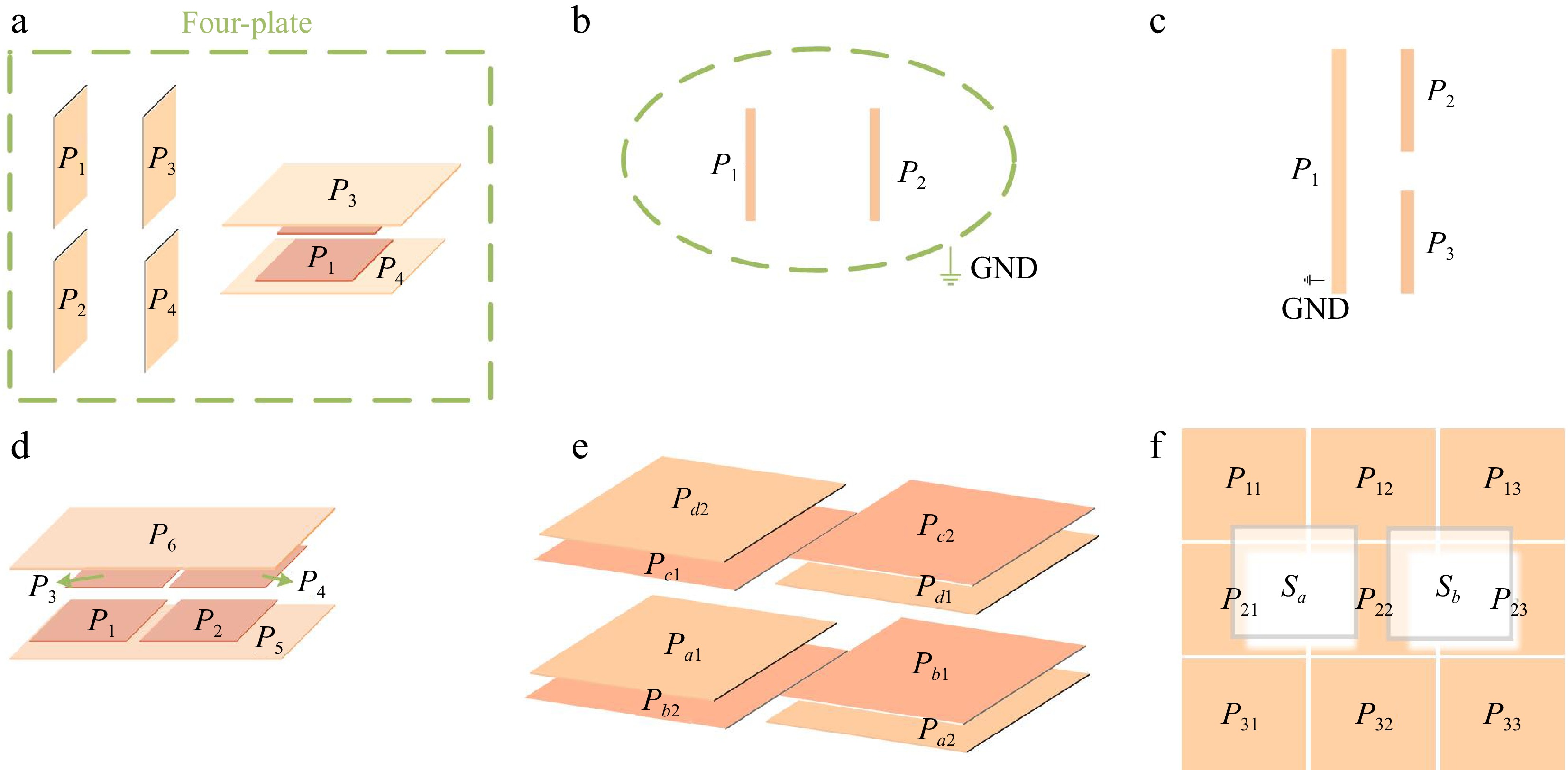
Figure 6.
The coupling structure researches of CPT systems. (a) Four-plate. (b) Two-plate. (c) Three-plate. (d) Six-plate. (e) Cross-coupling four-plate. (f) Matrix-type plate.
Compensation topology
-
In CPT systems, the coupling capacitance is generally measured in picofarads (pF) due to the limitations imposed by the plates and the dielectric constant. This results in considerable impedance within the circuit. To minimize reactive power loss and enhance transmission efficiency, inductive elements are employed to balance the plates.
Table 2 provides a summary of the current CPT compensation topologies. By optimizing voltage distribution, these compensation topologies effectively alleviate excessive voltage stress and enhance the system's degrees of freedom.
Table 2. The existing compensation topologies of CPT.
Compensation topologies Characteristics Ref. Inductive compensation (single L) 1. High-level compensation inductance;
2. Suitable for low-power, high-frequency applications.[48,49] LC compensation Resonant frequency can be effectively adjusted, but poor at adjusting to changing loads. [50−52] Higher resonance compensation LCL Better adaptability to load variations and misalignment. [53] CLLC Optimized system performance with high robustness. [54] LCLC 1. Bilateral LCLC compensation provides higher efficiency and better dynamic response;
2. Capable of maintaining stable power transfer over a wide range of load variations and misalignment.[55] As shown in Fig. 7, a novel compensation topology was proposed[56]. In this configuration, mutual inductance is utilized to modify the resonant frequency and augment coupling efficiency in this structure. It is suitable for dynamic and complex load conditions to enhance the load adaptability and reduce the plate voltage stress.
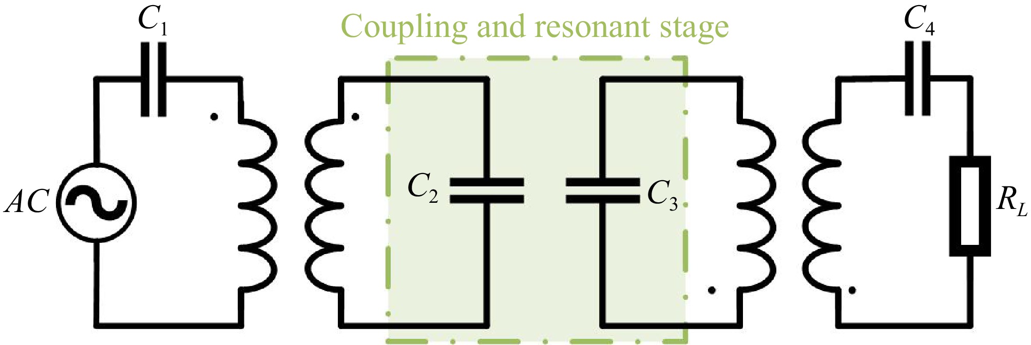
Figure 7.
A novel compensation incorporates coupling coils with mutual inductance.
Transmission performance of CPT
-
The CPT system is dual to the IPT system, and its transmission performance is influenced by similar factors as the IPT system, including coupling coefficient, frequency, and load.
Coupling coefficient
-
Similar to IPT systems, CPT systems are also influenced by the coupling coefficient. This coefficient is a measure of the strength of the electric field coupling between two plates and is mathematically defined as:
$ k = \dfrac{{{C_m}}}{{\sqrt {{C_1}{C_2}} }} $ (4) where, Cm is the mutual capacitance between the plates, C1 and C2 are the self-capacitances of the transmitting and receiving plates, respectively. Mutual capacitance Cm can be further expressed as:
$ {C_m} = \dfrac{{\varepsilon S}}{d}(1 + \dfrac{\delta }{d}) $ (5) here, d is the orthogonal distance between the polar plates, S is the overlapping area of the plates, and the dielectric constant of the medium is represented by ε. When the plate size is much larger than the spacing, it can be simplified to the classical formula.
The transmission distance is typically measured in centimeters, and efficiency is diminished with increasing plate separation due to heightened electric field strength and mutual capacitance. A nonlinear CPT system with reduced power attenuation can solve the output fluctuation of the CPT system at 13 MHz, but its coupling coefficient is easily affected by plate offset[57]. The University of New Brunswick proposed a method to detect the misalignment using electrode plates. The lateral misalignment of this method can reach 170 mm, but the dielectric constant affects its coupling capacitance[58]. A previous study found that water with a high dielectric constant is an effective medium for CPT, thereby the CPT system is suitable for underwater applications[59].
Frequency
-
Switches in CPT systems generally are operated in the MHz range to mitigate plate capacitance, affecting system power transfer efficiency. A novel CPT model for a frequency quadrupling inverter was proposed to reduce switching frequency fourfold[60]. Transmission performance is enhanced and the loss is reduced. Frequency splitting also arises in CPT systems, numerous research efforts have delved into and dissected the theory of frequency splitting within the context of diverse compensation configurations[61−63].
Load
-
Load variations have been shown to have a vital impact on the performance of CPT systems, necessitating design adjustments to accommodate diverse conditions. An LCC-compensated system with Maximum Power Point Tracking (MPPT) achieved 10 W power over a certain load range with about 70% efficiency[64]. In multi-load scenarios, a design for cold container charging used an isolated compensation topology for constant voltage output[65], and further research on LCLC compensation for dual-load systems showed low output current fluctuations with load changes[66]. In current research, different topologies are often used for relay functions that affect multi-load systems analysis[67,68].
Compared with the existing IPT system, the theoretical framework of CPT is still developing. The current CPT system offers distinct advantages, including a lightweight and thin structural design, adaptability to metal environments, and a high-frequency response. Additionally, the CPT system is characterized by the absence of eddy current loss and a strong resistance to magnetic field interference. Despite these benefits, the technology faces several challenges: the transmission power is limited and diminishes rapidly with increasing distance; the coupling mechanism is sensitive, leading to significant fluctuations in capacitance; and there is considerable electromagnetic radiation in high-frequency electric fields. These limitations hinder the advancement of CPT technology.
-
The HWPT system is integrated with the distinct spatial transmission characteristics of IPT and CPT, utilizing a complementary dual-channel strategy for non-contact power transmission. A magnetic field transmission channel is established via coupling coils, whereas coupling plates construct an electric field transmission channel. These different components work synergistically to upgrade the transmission performance.
Composition of the transmission channel of HWPT
-
The scheme integrates the coupling mechanisms and compensation topology associated with IPT and CPT into HWPT, forming a versatile and efficient power transfer system. Within this innovative configuration, the transmission channels can be classified into independent compensation channels using a series-parallel mechanism, and shared compensation channels functioning through an integrated mechanism.
Series-parallel channel
-
Researchers leveraged the electromagnetic field decoupling properties to isolate the coupled electric and magnetic fields in individual cases. These decoupled components are subsequently integrated into an HWPT system through series or parallel configurations. As shown in Fig. 8, the series configuration devised by San Diego State University integrated coils and plates. The transmission mechanism of this system is analyzed from equivalent circuits, ensuring power transmission through the two mechanisms[69].
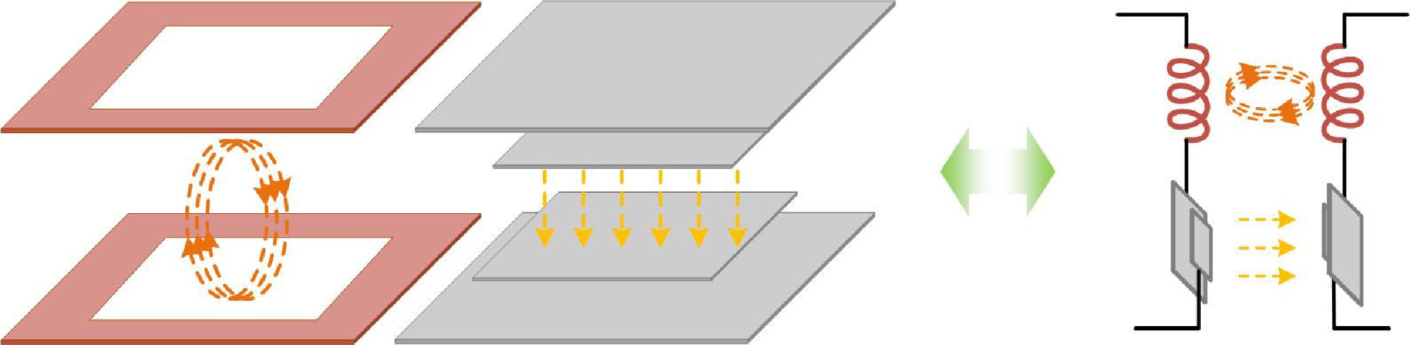
Figure 8.
Hybrid coupling structure with series configuration.
Southwest Jiaotong University (China) proposed the scheme of parallel connection of coils and plates. The two coupled components were integrated in a parallel configuration and subjected to series compensation[70,71]. The structural details of the proposed configuration are illustrated in Fig. 9.
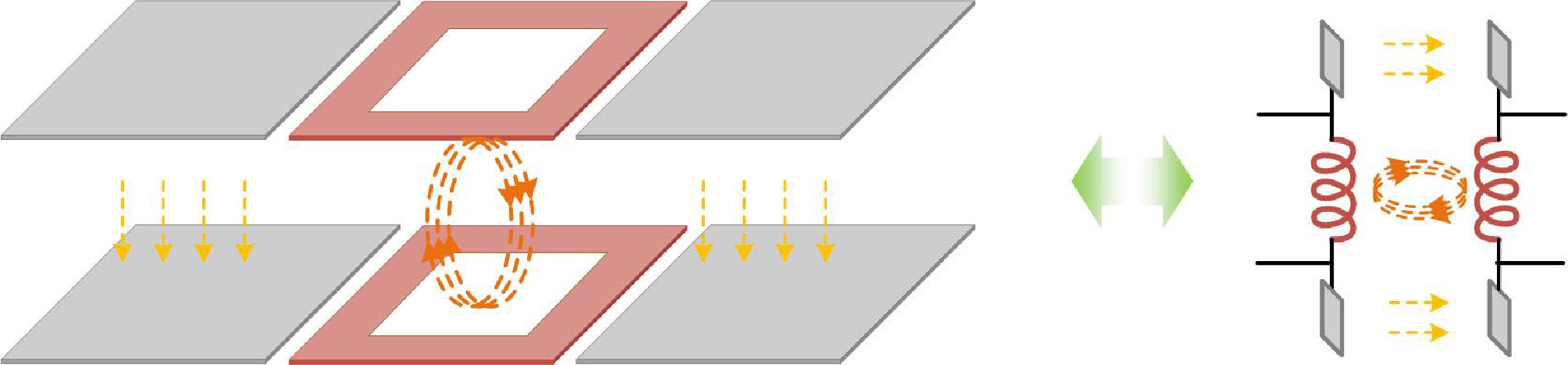
Figure 9.
Hybrid coupling structure with parallel configuration.
The systems utilize independent compensation structures, where IPT and CPT are designed separately but function concurrently. This topology is convenient to control and can enhance the reliability of the overall system[72]. Although transmission efficiency has been enhanced, the inherent defect of the design level has been exposed. That is spatial requirements and the compensation elements have an increasing trend.
Integrated channel
-
To solve the issue of the large spatial footprint, a novel compact capacitive-inductive integrated coupling mechanism was developed by researchers at Wuhan University (Wuhan, China). This co-planar configuration featuring integrated coil and plate arrangements[73], was engineered to minimize the dimensions while maintaining electromagnetic performance. Additionally, Jilin University (Jilin, China) also explored the integration of two coupling mechanisms on a printed circuit board, enclosing the coupling coil within a capacitive plate. This integration enabled the concurrent operation of the mechanisms, reducing circuit current and minimizing electromagnetic field leakage[74].
Compared to traditional separate configurations, the compact integrated approach creates a more space-efficient design. The coil and plate components are designed to be multi-functional in the integrated configuration. These elements not only constitute the main channels for magnetic and electric field coupling, but compensate for each other to minimize the element number[75−77], as shown in Fig. 10a. In addition to the embedded integrated structure, the layered design is the most widely used. Figure 10b illustrates the proposed integrated coupling mechanism, in which the minimal compensation elements are needed to achieve resonance at 1 MHz. The next goal was to achieve self-resonance below 2 MHz by strategically employing insulating and magnetic materials. A novel multi-layer structure design was proposed for HWPT[78], demonstrating its superiority in delivering a power output of 1 kW.
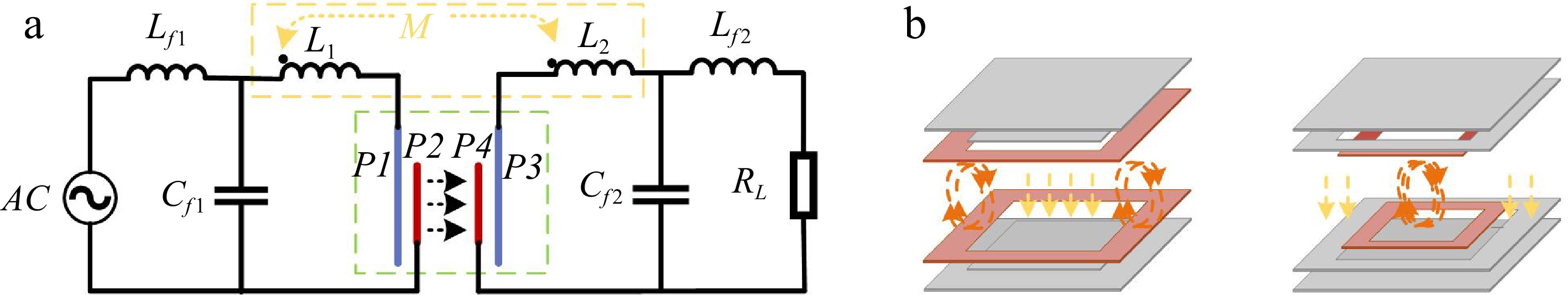
Figure 10.
Integrated coupling mechanism and shared compensation topology. (a) Shared compensation topology. (b) Coupling mechanisms.
Most of transmission channels are two-dimensional planar, and three-dimensional coupling is rare. In the actual design, a 3D heterogeneous HWPT transmission channel for multi-receiver spatial power delivery networks can be attempted. In addition, how to distribute the spatial position of coils and plates in the integrated structure of HWPT system will also be a major focus of future development.
Transmission performance of HWPT
-
The transmission performance of HWPT systems includes not only the independent characteristics of IPT and CPT systems but the synergistic interaction between them. The HWPT system is allowed to leverage the strengths for enhanced efficiency and flexibility by this dual-channel approach.
Transmission distance
-
Compared with single systems, transmission distance is significantly improved with HWPT systems. A novel HWPT system is proposed by the South China University of Technology (China), in which a parity-time symmetric circuit is utilized that can maintain a constant efficiency of 77% over a 1.4 m range[79]. As shown in Fig. 11 , the experiment found that compared with the traditional method, the operation distance of the HWPT system was extended by about 60%, and the efficiency over short distances was improved by about four times[80].
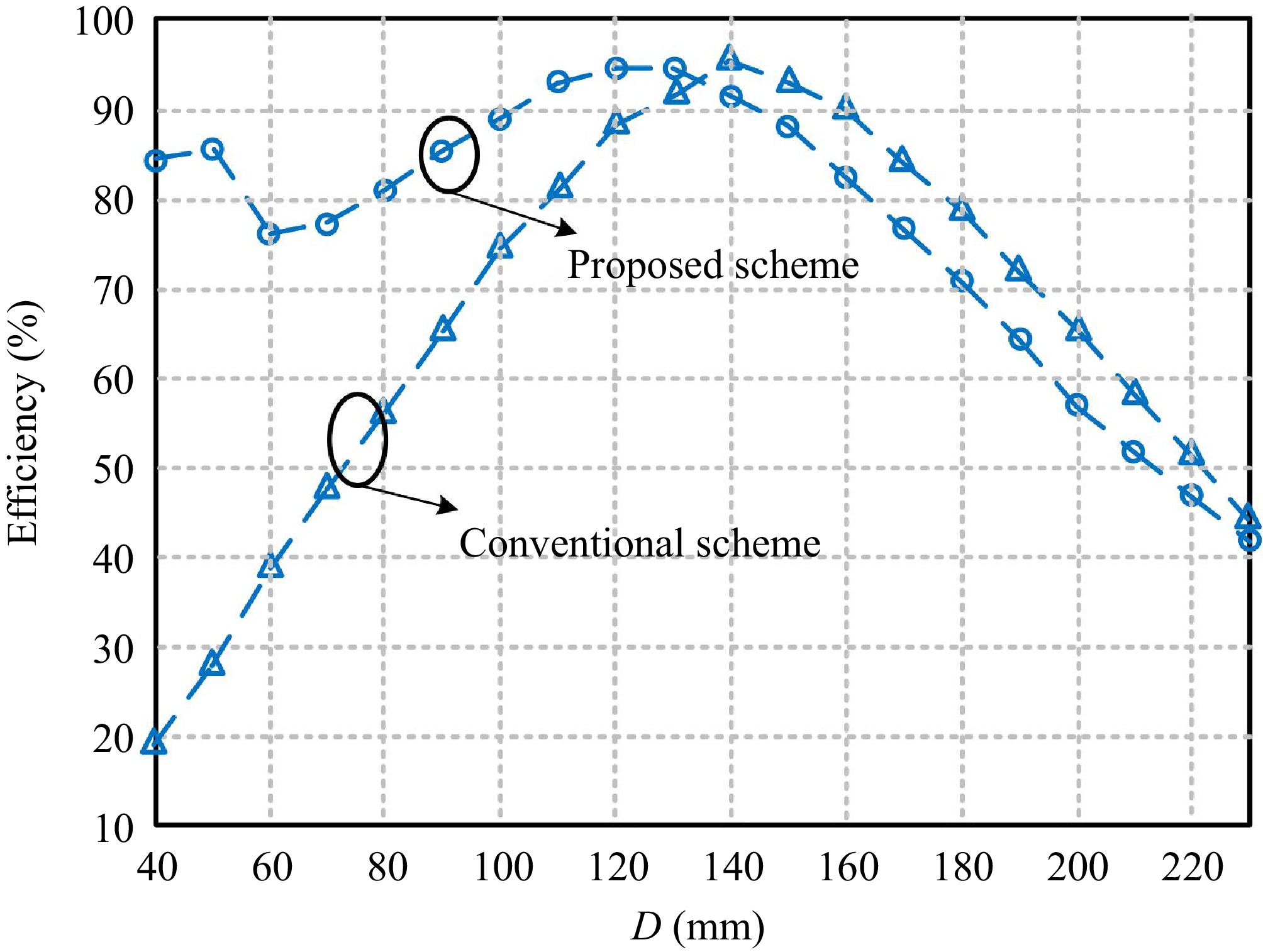
Figure 11.
The relationship between D and η between proposed systems[80].
Controlling ratios
-
By controlling the power allocation ratio between the IPT and CPT channels, the output power can be optimized to achieve maximum transmission efficiency. The output power is distributed based on the proportion of power allocated to the channels, which can be mathematically expressed as shown in Eqn (5).
$ {P_{HWPT}} = {\alpha _1}{P_{IPT}} + {\alpha _2}{P_{CPT}} $ (6) where, α1+ α2 = 1.
The distributions of IPT and CPT typically are operated with a 1:1 power ratio, where the total output power is the sum of the individual contributions[81−83]. However, the power distribution ratio is not fixed and can be adjusted to suit specific application requirements. There is a study which suggested that the CPT system contributes less significantly, accounting for approximately 33.3% of the total power[84]. Furthermore, Alexandria University (Alexandria, Egypt) optimized power distribution where IPT contributed the remaining 82.35%[85]. Different from other control ratios, a 5.2 power ratio (81% IPT, 19% CPT) HWPT system is proposed, in which the misalignment ability is significantly improved[86].
Load
-
In alignment with the single-mode system, the HWPT system is also influenced by load parameters. However, there are few studies focusing only on load variation in HWPT. Investigating the factors that affect load on transmission performance is crucial for establishing a foundation for comprehensive loss analysis of the entire system. This research examines the relationship between load variation and output power, analyzing both long-distance and short-distance scenarios[87]. It is revealed that output power exhibits a linear relationship with load resistance over long distances, while a more pronounced nonlinear relationship emerges as the distance decreases. Additionally, it is observed that higher resistance levels correspond to greater nonlinearity in output power.
-
HWPT is a versatile and efficient solution for diverse applications. Despite being in its early stages and facing several challenges, HWPT is supported by ongoing advancements and research that highlight its significant potential, promising future innovations, and broad applications in WPT.
Unique advantages of HWPT
-
HWPT systems have been shown to deliver superior power transmission and optimized performance compared with the single-mode WPT. This advancement provides several advantages, including enhanced tolerance to misalignment, the capability to navigate conductive barriers, reduction of frequency splitting, and improved electromagnetic safety. (a) Enhanced tolerance to misalignment[88]: as illustrated in Fig. 12, the tolerance to misalignment has significantly improved compared to traditional systems, resulting in enhanced transmission power and efficiency[89]. This improvement is fundamentally attributed to the complementary effects of magnetic and electric fields. (b) Capability to overcome conductive barriers: the HWPT systems effectively address power degradation caused by eddy current loss and the shielding effect present in traditional WPT systems. For instance, utilizing a metal barrier as part of the coupling mechanism offers a novel solution for ensuring stable power supply to equipment operating in metal environments[90]. (c) Reduction of frequency splitting[91]: by optimizing the total coupling coefficient of the system, the HWPT system enhances the overall coupling coefficient, leading to more stable energy transmission. (d) Improved electromagnetic safety[92,93]: the incorporation of an aluminum plate significantly restricts the distribution of the magnetic field compared to a single IPT system, resulting in a marked reduction in electromagnetic field leakage.
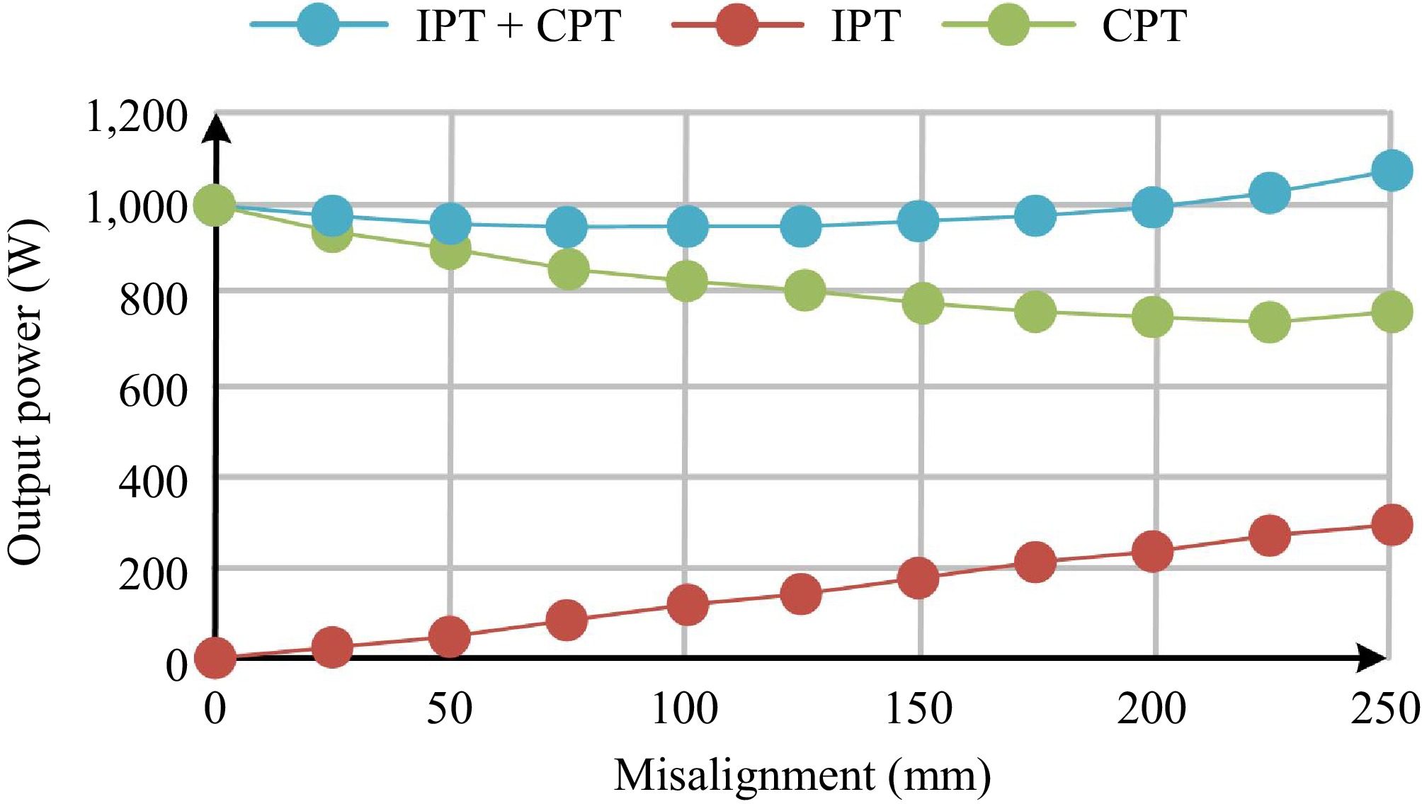
Figure 12.
The unique advantages of HWPT, enhanced tolerance to misalignment.
An analysis of IPT, CPT, and HWPT systems is summarized in Table 3. Through comparison, it is found that HWPT has more significant flexibility and applicability, which is a key focus of future research.
Table 3. Analysis of IPT, CPT, and HWPT systems.
Technical indicators IPT CPT HWPT Transmission channel Magnetic 
Electric 
Magnetic and Electric Fields 
Frequency At kHz (85 kHz is the most used) MHz Depend on the form of coupling
between IPT and CPT (kHz ~ MHz)Distance Well (Range from centimeters to meters) Poor (10−100 mm) Better Electromagnetic shielding effect Low (need external shielding) Medium High Ability to pass through obstacles Low Medium High Others Easy to cause Eddy current problems Electric field leakage problem 1. Complementary functions of IPT and CPT;
2. Suppression of Frequency Splitting;
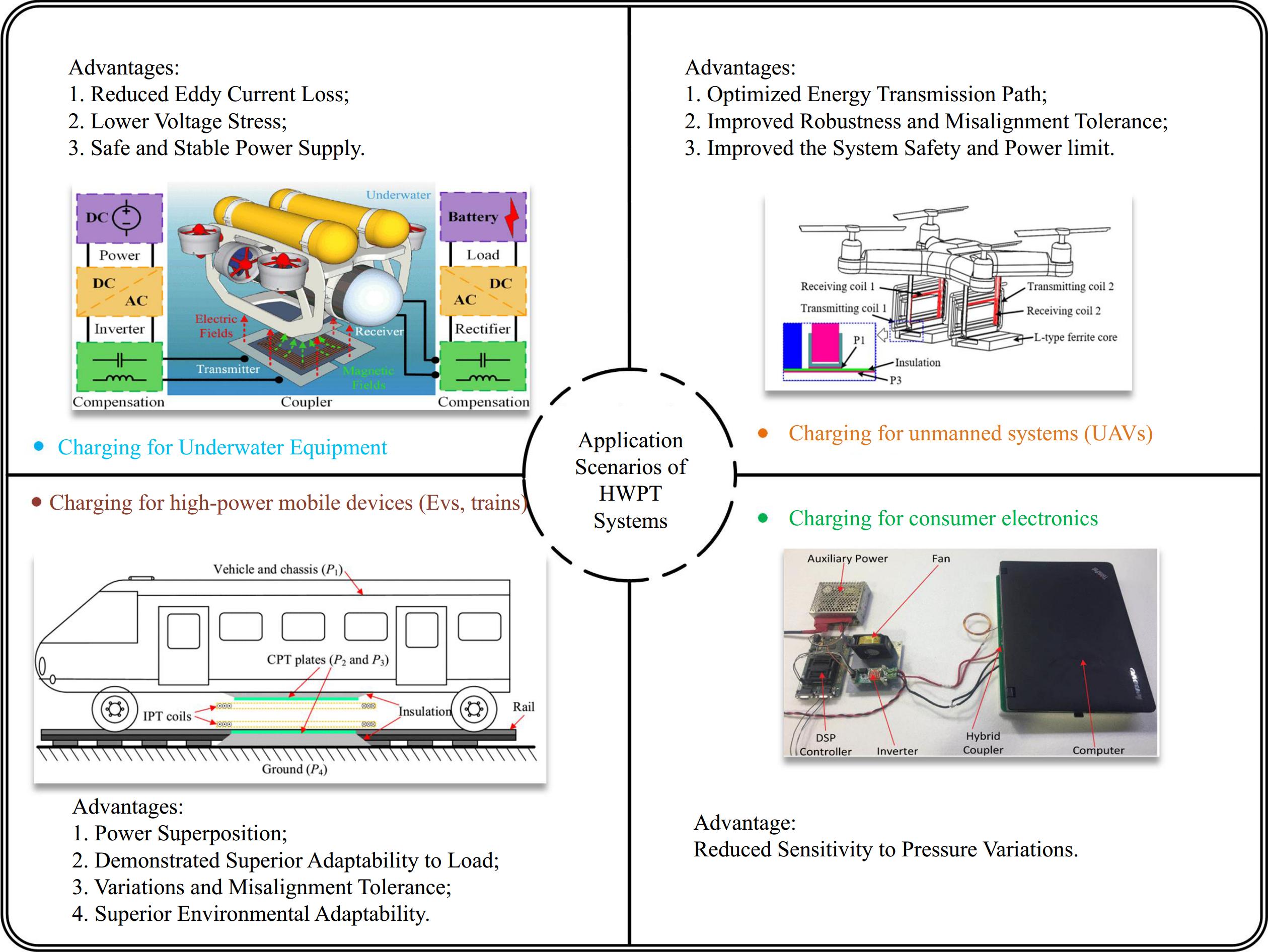
3. Misalignment Tolerance is increasedApplication scenarios of HWPT
-
The distinctive combination of inductive and capacitive coupling makes it particularly well-suited for high-power mobile devices[94−96], consumer electronics[97,98], underwater equipment[99], and unmanned systems[100]. The various application scenarios are depicted in Fig. 13. HWPT can be also explored for the online transmission line monitoring device and in industrial robotics[101]. Given its unique advantages, there is potential to explore the simultaneous power supply capabilities of multiple HWPT devices and monitor the pouring status of concrete and other materials in buildings.
Existing challenges and solutions
-
As an emerging research domain, HWPT systems have revealed several challenges. These challenges are associated with the distribution of uneven power distribution, a high operating frequency with low transmission efficiency, and a lack of dynamic monitoring capability.
Non-uniform power distribution
-
Contemporary investigations on HWPT are focused on developing hybrid structures for directional power transmission based on the equivalent circuit model. To achieve the best transmission performance, an uneven power distribution exists. For online transmission line monitoring devices, it is necessary to provide a diversified and stable energy supply for multiple locations and loads, particularly in metal environments. Consequently, comprehensive analysis of the spatial energy flow characteristics of magnetic and electric field coupling from the perspective of electromagnetic interaction has been essential. The coupling mechanism of omni-directional electromagnetic co-existence can be constructed to explore the relationship between optimal spatial transmission performance and the electromagnetic proportion. The space ratio can be improved by adjusting the energy of the electric and magnetic fields to eliminate the impact of the metal environment.
High operating frequency, and low efficiency
-
The increase in resonant frequency has led to higher switching losses in power electronics, reducing the overall efficiency. In HWPT systems, converters operating at elevated frequency levels are increasingly important, making optimization of the power electronics a critical focus. Moreover, the majority of existing systems are confronted with challenges such as eddy current loss and frequency splitting, caused by the mutual coupling between electric and magnetic field coupling mechanisms. These problems will diminish the transmission power. Developing new materials to enhance the dielectric constant and optimizing the coupling mechanism remain significant hurdles to address.
Lack of dynamic monitoring capability
-
Current research is concentrated on static analysis of the systems to a particular degree, exhibiting a dearth of capacity to dynamically monitor alterations in pivotal parameters such as system loads and coupling coefficients. Consequently, the integration of artificial intelligence and intelligent sensing technologies is proposed to facilitate real-time monitoring of the systemic state. It can be integrated with artificial intelligence and intelligent sensing technologies. This will be helpful in facilitating the automatic detection of subtle changes in critical parameters, prompting real-time adjustments to ensure adaptability and stability. This enhancement of operational efficiency in dynamic external and internal environments is a key benefit.
-
HWPT holds great promise for the future of WPT technology. In this paper, based on the recent technological advances, a comprehensive comparison and analysis is presented, including the design of power transmission channels and transmission performance characteristics in IPT, CPT, and HWPT. Furthermore, an exploration of the prospective applicable scenarios of HWPT is undertaken, alongside a detailed discussion of the technical challenges and potential solutions. By reviewing and evaluating HWPT, this study aims to provide a valuable reference for researchers and designers in further research.
This work was supported in part by the National Natural Science Foundation of China (Grant No. 52307008), in part by the University-Industry Collaborative Education Program between Universities in Hebei Province and Shijiazhuang (Grant No. 241060041A), in part by the Science and Technology Project of Hebei Education Department (Grant No. CXZX2025056), and in part by the S&T Program of Hebei (Grant No. 225676163GH).
-
The authors confirm contribution to the paper as follows: Study conception and design: Dai Z, Zhang X; data collection: Sun M, Wang H, Zhai Y, Song J, Ye S, Zhang M; investigation: Ding X, Chen Y; analysis and interpretation of results: Dai Z, Sun M, Wang H, Zhai Y; draft manuscript preparation: Sun M, Wang H; manuscript review and editing: Dai Z, Sun M. All authors reviewed the results and approved the final version of the manuscript.
-
All data included in this study are available upon request from the corresponding author.
-
The authors declare that they have no conflict of interest.
- Copyright: © 2025 by the author(s). Published by Maximum Academic Press, Fayetteville, GA. This article is an open access article distributed under Creative Commons Attribution License (CC BY 4.0), visit https://creativecommons.org/licenses/by/4.0/.
-
About this article
Cite this article
Dai Z, Sun M, Chen H, Ding X, Wang H, et al. 2025. Hybrid wireless power transfer: a review. Wireless Power Transfer 12: e017 doi: 10.48130/wpt-0025-0014 

Hybrid wireless power transfer: a review
- Received: 20 February 2025
- Revised: 23 April 2025
- Accepted: 12 May 2025
- Published online: 26 June 2025
Abstract: Inductive power transfer (IPT) and capacitive power transfer (CPT) have been extensively studied and applied in wireless power transfer (WPT). In the process of system design and analysis, only the characteristics of magnetic or electric fields are considered. This means that only magnetic or electric field coupling is used for transmitting power. As research on WPT continues to deepen, particularly in areas such as achieving high power density and a high distance-to-diameter ratio, a distinct technical advantage is lost. However, a hybrid wireless power transfer (HWPT) scheme that integrates magnetic field coupling and electric field coupling simultaneously, is garnering increasing attention. In this paper, a comprehensive analysis was conducted on the structural configurations and system transmission characteristics of IPT, CPT, and HWPT, and their work principle and main influencing factors were clarified. Furthermore, the potential technical advantages, applicable scenarios, and prevailing challenges of HWPT systems were discussed in detail. Based on the review and analysis of the latest progress, HWPT technology has significant potential for growth and is poised to become the dominant direction of future WPT development.