


-
Inductive power transfer (IPT) systems for wireless charging of electric vehicles (EVs) in the present day generally utilize a pair of coupled coils, one on the transmitting side (the charging station) and the other on the receiving side (the vehicle) in order to facilitate the transfer of power wirelessly through an air gap between them[1−3]. To analyze the maximum power transfer efficiency obtainable in such systems, it is essential to estimate the coefficient of magnetic coupling between the coils, along with their self-inductance and individual quality factors[4,5]. At the initial stage, one can use online applications that estimate the coils' parameters utilizing empirical and mathematical formulae in order to calculate parameters such as self-inductance, the required number of turns for a certain value of inductance, mutual inductance and the coupling coefficient based on the self-inductance of two coupled coils[6−9]. A detailed theoretical analysis and calculation method has been proposed, where the mutual inductance was considered to be dependent on the coils' geometry, the number of turns of each coil and the air gap between the primary and secondary coils[10]. Indeed, all these factors play a crucial role in determining the coupling coefficient between the coils. However, these approaches do not consider the effects of ferrites and shielding materials that a real-life system would normally incorporate and, therefore, are not accurate methods for parameter estimation in an EV charging system. In order to simulate and incorporate the effects of ferrites and shielding materials, the three-dimensional (3D) finite element method (FEM) is advantageous, since it helps in solving complex differential equations in all three dimensions, thus modeling real-world scenarios where phenomena occur in all three spatial dimensions. Unfortunately, 3D FEM simulations are time-consuming and computer resource-intensive, since even a small change in the parameters, such as adding a single turn to one of the coils, requires the entire simulation to be re-run. To minimize the calculation time, a polynomial-based approach has been studied and incorporated[11]. This approach relies on calculating the phase angle tangent value of the receiving side's circuit impedance via the reflected impedance. The solution for estimation was primarily focused on achieving constant current control over the IPT system and did not include any other measurements of the receiving side. A method for estimating the mutual inductance, coupling coefficient and power transfer efficiency in a dynamic wireless power transfer system has also been recently proposed[12]. The authors utilized a single 3D FEM simulation of the magnetic field generated by a transmitting structure in the vertical Z-axis that they further combined with other parameters to obtain an estimated result of the mutual inductance. The error was 1.56% in standard situations when compared with the experimental results, which considered a dynamic change in the receiver's position over the transmitter. The maximum error in this situation was 3.14% when the width of the receiver varied, resulting in a 2.35% median error. However, the changes in the air gap were not considered in the experimental verification. A semi-analytical approach for calculating the self and mutual inductance of hexagonal spiral coils used in wireless power transmission (WPT) systems was introduced where the calculation method is based on the Biot–Savart Law and avoids the formation of complex integrals, offering a simplified solution[13]. The authors validated their approach through an experimental study, finite element analysis and comparisons with existing methods. For instance, the self-inductance of a hexagonal coil with a 20-cm side length was calculated with an error of 2.8% compared with the experimental data. Similarly, for a typical EV application with a 100-mm air gap between the coils, the mutual inductance was determined with an error of 5.84%. While the method provides acceptable error rates for the large coils typical in high-power applications, it requires higher iteration numbers to achieve the same error rate for smaller coils. This is because the ratio of neglected area to total area is more significant in small-sized coils, potentially leading to increased computational complexity and longer solution times. Additionally, as the distance between the coils increases, the percentage error of the calculated mutual inductance value tends to rise, likely due to increased leakage flux. Another approach introduced a practical coupling coefficient estimation method for a real system based on bifurcation phenomena[14]. The system is temporarily operated in bifurcation, short-circuiting the load, and measuring the zero-phase angle frequencies on the primary side. While the method is unique, it operates decently within a certain range of the coupling coefficient (0.08 to 0.36) and has a median error of 3.62% in this range.
In this paper, we propose a real-time solution for estimating coupled coil parameters which is realized as a web-based or standalone application. A screen capture of the graphical user interface (GUI) of this application is presented in Fig. 1. The real-time estimator utilizes curves plotted from the values of the numerically estimated coupling coefficients of an 11-kW IPT system which were obtained for several discrete values of the air gap between the coils and their number of turns. The main novelty of the proposed estimator in comparison with the existing methods described previously is that it solves quadratic and cubic curve-fitting functions in real time to estimate the coils' parameters, Q-factor values, and power transfer efficiency instantly. Unlike most coil parameter calculators and estimators available online, the proposed estimator of coupled coil parameters employs a hybrid approach that combines the results of a single initial 3D FEM simulation with equations and formulae. This approach makes sure that the side-effects of field distributions as well as the ferrite materials and metals used for shielding etc. are well represented. Thus, it provides an estimation that is closer to real-world measurements than other approaches that simply rely on formulae. We also experimentally verify the values of the coupling coefficient of a laboratory prototype of an 11-kW IPT system and compare them with the numbers predicted by the estimator to analyze their correlation.
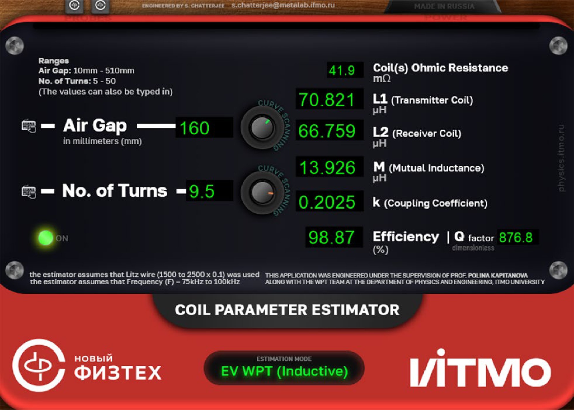
Figure 1.
GUI of the standalone version of the real-time estimator of the parameters for coupled coils in an 11-kW wireless charging system.
-
The equivalent circuit of the electromagnetic section of an IPT system can be represented by a T-network, as illustrated in Fig. 2. From an analytical and electrical circuit theory approach, the power transfer efficiency refers to the fraction of power transferred from the primary to the secondary coil[14]. To derive this efficiency, we consider the power transferred from the primary coil to the secondary coil through the mutual inductance M, with the addition of capacitors C1 and C2 on the primary and secondary sides, respectively, as part of the matching networks[15,16]. These capacitors compensate for the reactive components, improving the efficiency of power transfer.
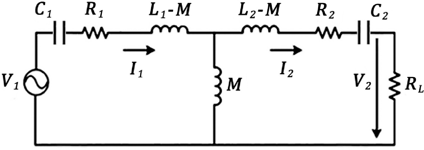
Figure 2.
Equivalent circuit of the electromagnetic section of the IPT system.
The input power of the primary coil Pin can be written as:
$ {P}_{\text{in}}={I}_{1}^{2}\left({R}_{1}+{\rm{Re}}\left({Z}_{\text{ref}}\right)\right), $ (1) where, I1 is the primary coil current, R1 is the ohmic resistance of the primary coil and Re(Zref) is the real part of Zref, which is the reflected impedance from the secondary side, given by:
$ Z_{\text{ref}}=\dfrac{\mathrm{\omega}^2M^2}{R_2+R_L+j\left(\mathrm{\omega}L_2-\dfrac{1}{\mathrm{\omega}C_2}\right)} $ (2) where,
$ \mathrm{\omega } $ $ {P}_{\text{rf}}=\dfrac{{\mathrm{\omega }}^{2}{M}^{2}{R}_{L}{I}_{1}^{2}}{{\left({R}_{2}+{R}_{L}\right)}^{2}+{\left(\mathrm{\omega }{L}_{2}-\dfrac{1}{\mathrm{\omega }{C}_{2}}\right)}^{2}} $ (3) The power transfer efficiency can then be formulated as the ratio of power transferred to the secondary coil to the input power of the primary coil.
${\mathrm{\eta }}_{\text{rf}}=\dfrac{{P}_{\text{rf}}}{{P}_{\text{in}}}=\frac{\dfrac{{\mathrm{\omega }}^{2}{M}^{2}{R}_{L}}{{\left({R}_{2}+{R}_{L}\right)}^{2}+{\left(\mathrm{\omega }{L}_{2}-\dfrac{1}{\mathrm{\omega }{C}_{2}}\right)}^{2}}}{{R}_{1}+\dfrac{{\mathrm{\omega }}^{2}{M}^{2}}{{\left({R}_{2}+{R}_{L}\right)}^{2}+{\left(\mathrm{\omega }{L}_{2}-\dfrac{1}{\mathrm{\omega }{C}_{2}}\right)}^{2}}}$ (4) Assuming resonance conditions
$ \left(\mathrm{\omega }{L}_{2}=\dfrac{1}{\mathrm{\omega }{C}_{2}}\right) $ $ {\mathrm{\eta }}_{\text{tr}} $ $ {\mathrm{\eta }}_{\text{tr}}=\dfrac{{P}_{\text{tr}}}{{P}_{\text{in}}}=\dfrac{\dfrac{{\mathrm{\omega }}^{2}{M}^{2}{R}_{L}}{{\left({R}_{2}+{R}_{1}\right)}^{2}}}{{R}_{1}+\dfrac{{\mathrm{\omega }}^{2}{M}^{2}{R}_{L}}{{\left({R}_{2}+{R}_{1}\right)}^{2}}} $ (5) $ {\mathrm{\eta }}_{\text{tr}}=\frac{{\mathrm{\omega }}^{2}{M}^{2}{R}_{L}}{{\left({R}_{2}+{R}_{1}\right)}^{2}+{\mathrm{\omega }}^{2}{M}^{2}{R}_{L}} $ (6) The quality factors for the primary and secondary coils, which are Q1 and Q2 respectively, considering the capacitances, are defined as
$ {Q}_{1}=\dfrac{\omega {L}_{1}}{{R}_{1}},\text{}{Q}_{2}=\dfrac{\omega {L}_{2}}{{R}_{2}+{R}_{L}} $ (7) The coupling coefficient k between the primary and secondary coils is defined as shown in Eq. (8)[17]:
$ k=\dfrac{M}{\sqrt{{L}_{1}{L}_{2}}} $ (8) Using these definitions and assuming that the system is under resonant conditions
$ \left(\mathrm{\omega }{L}_{1}=\dfrac{1}{\mathrm{\omega }{C}_{1}},\mathrm{\omega }{L}_{2}=\dfrac{1}{\mathrm{\omega }{C}_{2}}\right) $ $ {\eta }_{\text{tr}}=\frac{{k}^{2}{Q}_{1}{Q}_{2}}{1+{k}^{2}{Q}_{1}{Q}_{2}} $ (9) For the geometric mean of the quality factors
$ {Q}_{\text{gm}}=\sqrt{{Q}_{1}{Q}_{2}} $ $ {\mathrm{\eta }}_{\text{tr}}=\frac{{k}^{2}{Q}_{\text{gm}}^{2}}{1+{k}^{2}{Q}_{\text{gm}}^{2}} $ (10) The derived expression Eq. (10) is applied in the proposed real-time estimator to evaluate the power transfer efficiency.
As shown in Fig. 3, we consider a 3D FEM model of an IPT system for the wireless charging of EVs that is composed of the transmitting side and the receiving side, as previously described by Bosshard et al.[19]. The authors claim that it is suitable for applications where compliance with the standard SAE J2954 is required[15]. The primary and secondary coils are placed on top of multiple ferrite rods known as I-cores made of manganese–zinc N87 material with a relative permeability of
$ {\mu }' $ 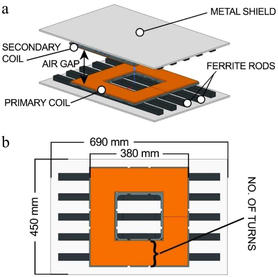
Figure 3.
3D FEM model of the IPT system under consideration.
Table 1. Initial data provided for 3D FEM simulation of the IPT system.
Initial data Value Dimensions (metal screen) 450 mm × 690 mm × 5 mm Dimensions (coil) 380 mm × 380 mm × 5 mm Dimensions (ferrite) 126 mm × 28 mm × 20 mm (25 pieces) No. of turns 9.5, 10.5, ... 15.5 Air gap (mm) 160, 180, ... 300 Metal screen material Aluminum Coil material Copper (Litz wire, 0.1 mm × 2,500 strands) Ferrite material Manganese–zinc (N87) Frequency 85 kHz Boundary conditions Tangential fields (50% padding on all sides) Solver type Eddy current solver (low frequency) Output Discrete data table -
There are two processes involved: the simulation process, which is a one-time process with multiple parametric steps for obtaining results for each of the discrete values of the air gap and the number of turns, and the estimation process, which combines the simulated results with polynomial curve-fitting equations in order to estimate the values of the self-inductances of the coils, their mutual inductance, the coupling coefficient and the power transfer efficiency of the IPT system. Figure 4 is a flowchart that illustrates the processes and steps involved in them.
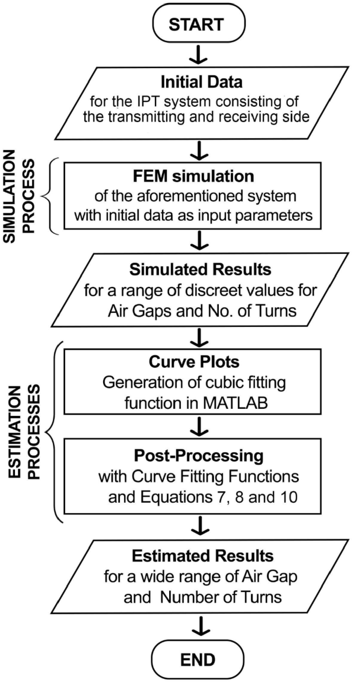
Figure 4.
Flowchart of the simulation and estimation processes.
Simulation process
-
FEM simulations require a set of initial parameters to accurately model and solve the problem at hand, which primarily include the geometry of the 3D FEM model, the material properties, the boundary conditions, mesh information, the type of solver and its settings, the simulation parameters and the output requirements. Table 1 shows the initial parameters that are used to simulate the system. The 3D FEM simulations were performed in Ansys Maxwell, utilizing the eddy current solver step by step for each value within the ranges of the air gap and the number of turns at a fixed frequency of 85 kHz. The tetrahedral mesh of the 3D FEM model has a total of 1.85 million elements, and 10 convergence passes are performed with 30% refinement per pass. The eddy current solver in Ansys' electromagnetism module enables the solution of problems using the "eddy current" approximation[22]. This approach is valid for sufficiently good conductors with low-frequency time-varying fields, where the displacement currents are negligible compared with the current density. As a result of the numerical simulation, we obtained discrete values for L1, L2, M, k and R1, R2 for the range of air gaps and the number of turns in the coil. The simulated results for self-inductance and mutual inductance as a function of the number of turns and the coupling coefficient as a function of the air gap are demonstrated in Fig. 5 using markers.
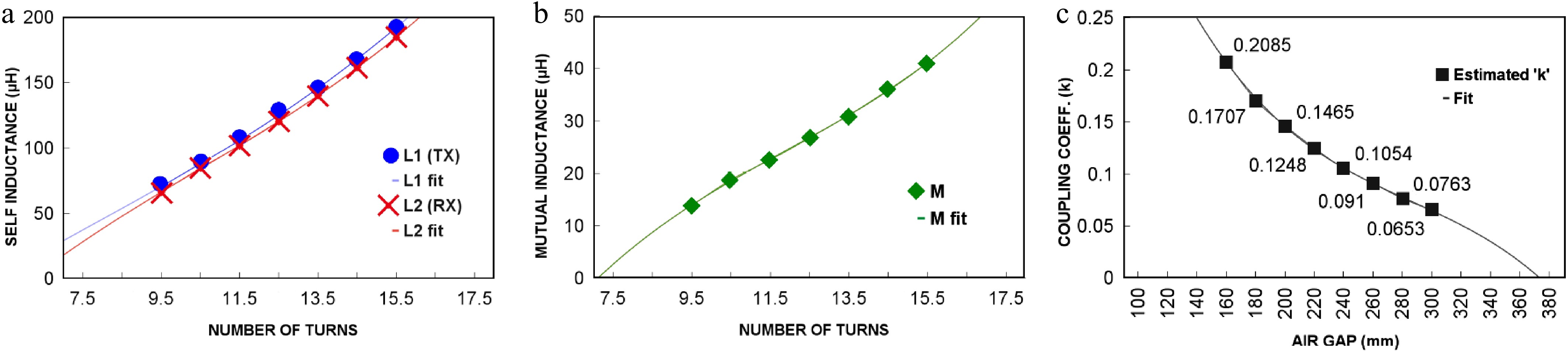
Figure 5.
Relationships among the crucial parameters: (a) relationship between the self-inductance of individual coils and the number of turns, (b) relationship between mutual inductance and the number of turns, and (c) relationship between the coupling coefficient and the air gap.
Estimation process
-
The results of the numerical simulations were exported in a tabular format to MATLAB for obtaining curve-fitting functions, which enabled us to statistically define the relationships among the self-inductances (L1, L2), mutual inductance (M) and the number of turns (n) for the variation of the coupling coefficient (k) due to the change in the air gap (x). The self-inductance of a coil has a direct relationship with the following factors: the number of turns, the area and geometry of the coil, and the coil's material. The relationship between the coils' self-inductances (L1, L2) and the number of turns (n) is presented in Fig. 5a as a spline curve. They are expressed in the form of two quadratic fitting functions for the primary coil as follows:
$ L_1=A_1n^2+B_1n-C_1 $ (11) where, A1 = 0.697, B1 =2.745, and C1 =18.161, which are the optimized curve fitting values for the primary coil.
For the secondary coil, we have the following:
$ {L}_{2}={A}_{2}{n}^{2}+{B}_{2}n-{C}_{2}, $ (12) where, A2 = 0.568, B2 = 5.371, and C2 = 35.504, which are optimized curve fitting values for the secondary coil. The curves show that as the number of turns increases, self-inductance also increases for both the coils, with a slight difference between them, which could be due to the parasitic effects (ferrites, dielectrics and metal shield) of the other elements present in the transmitting and receiving sides. An estimated relationship between the mutual inductance (M) and the number of turns (n) is presented in Fig. 5b as a spline curve and can also be expressed using the following quadratic fitting function:
$ M=A_3n^2+B_3n-C_3 $ (13) where, A3 = 0.0766, B3 = 2.497, and C3 = 16.880, which are the optimized curve fitting values. The curve is slightly nonlinear, indicating that mutual inductance increases at a slightly accelerating rate with more turns during a linear period in the mid-range values of the number of turns. The air gap plays a critical role in determining the coupling coefficient between the coils and their relationship is presented in Fig. 5c as a spline curve that can be expressed using the following cubic fitting function:
$ k=A{x}^{3}+B{x}^{2}-Cx+D $ (14) where, A = 8.544 × 10⁻⁹, B = 1.027 × 10⁻⁵, C = 4.308 × 10⁻³, and D = 6.639 × 10⁻¹ which are the optimized curve fitting values for the system. In this curve, one can see that the relationship between the air gap and the coupling coefficient is inversely proportional and nonlinear, which can be attributed to the complex nature of electromagnetic interactions. As the air gap increases, the magnetic field's strength decreases more rapidly, leading to a nonlinear decrease in the coupling coefficient. This behavior is typical in systems involving inductive coupling, where the efficiency of energy transfer diminishes at an accelerating rate as the distance between the components grows. It is also necessary to mention that we are using a cubic fitting function for the air gap vs. coupling coefficient plot because of the nonlinear nature of the curve, but for the other plots, we can use a quadratic fit. The fitted curve plots form the basis of the estimation process and the real-time estimator's working principle, as any value within the simulated range and even beyond the simulated range can be further combined with equations in order to estimate the parameters of the IPT system. The individual Q-factors of the primary and secondary coils can be calculated using the individual self-inductances obtained from Eqs (11) and (12), using Eq. (7). The power transfer efficiency is calculated using (10), and the entire set of processes required for the estimation of the coupled coil parameters are consolidated into a software application using the Python programming language, which acted as a base for all other versions of this software (i.e., the online version accessible publicly as "Coil Parameter Estimator" and the offline version, which is available upon request)[23]. The estimated results are obtained almost instantly in 2 ms through the software application, whereas the FEM simulation for the same would have taken an estimated 75 min in a PC running Windows 11, with an 8-core AMD Ryzen 7 CPU and 16 GB of RAM. Our proposed approach has several advantages compared with another fast and general method by Song et al.[12]. First, it considers the changes in the width of the primary coil and the secondary coil that can result from an additional number of turns. Second, it considers changes in the air gap, which directly affect the coupling coefficient. It also offers a faster computation time, which is ~2 ms, while also consuming fewer computer resources compared with ~0.6 min in Song et al.'s method, which used more computer resources.
In Fig. 6, we visualize the estimated power transfer efficiency (
$ {\eta }_{\mathrm{t}\mathrm{r}} $ $ {\eta }_{\mathrm{t}\mathrm{r}} $ 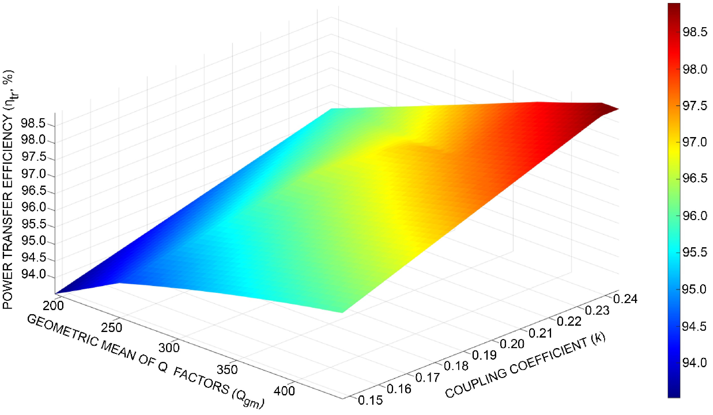
Figure 6.
Power transfer efficiency $ {(\eta }_{\mathrm{t}\mathrm{r}}) $ as a function of the geometric mean of the Q-factors $ \text{(}{Q}_{\mathrm{g}\mathrm{m}}) $ and the coupling coefficient $ \text{(}k) $ of the coupled coils of an 11-kW IPT system for EVs obtained with the proposed real-time estimator.
-
To determine whether the values obtained from the real-time estimator correlate with the measured real-world values, an experimental study was performed on a fully constructed laboratory prototype of the IPT system shown in Fig. 7a. The coils on the transmitting and receiving sides of the constructed IPT system have 10.5 turns each and are placed on 3D-printed Poly-lactic Acid (PLA) coil holders with grooves in them which help to maintain the spiral geometry of the turns. The coils, with their coil holders, are placed on top of parallel columns of ferrite rods with five ferrite rods per column and five columns per side, totaling 25 ferrite rods per side. These rods are secured to a custom-made aluminum metal screen on each side using 3D-printed PLA holders and dielectric nuts and bolts made of nylon. The air gap between the coils can be adjusted in steps of 160, 220, and 280 mm using three pairs of fiberglass slabs to keep the receiving side perpendicular to the transmitting side, ensuring that the air gaps are maintained. The schematic diagram of the experimental setup is shown in Fig. 7b. We used a two-port vector network analyzer (VNA) to obtain the Z-parameters of the IPT system. Port 1 of the VNA is connected to the coil terminals on the transmitting side and Port 2 is connected to the coil terminals on the receiving side using suitable high-frequency coaxial cables and standard radiofrequency SubMiniature version A (SMA) connectors. During the experimental study, we measured the Z-parameters for three discrete values of the air gap. From the measured data, one can extract the self-inductance of coils (L1, L2) and the mutual inductance (M) between them from the imaginary part of the measured Z-parameters as follows.
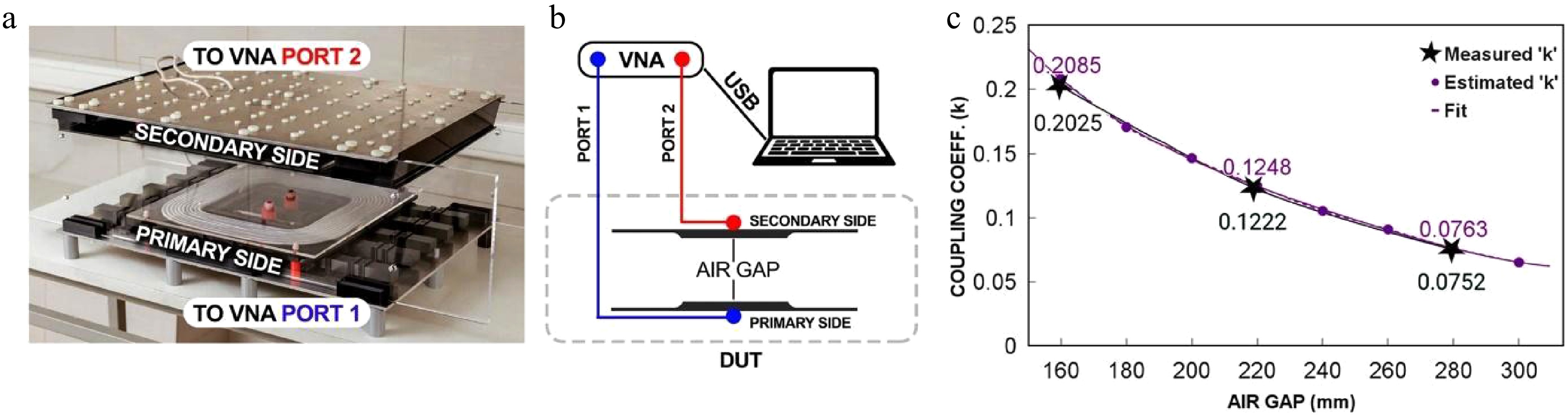
Figure 7.
(a) Photograph of the laboratory prototype of an 11- kW IPT system for EVs. (b) Schematic diagram of the experimental setup. (c) Measured and estimated dependence of the coupling coefficient as a function of the air gap between the transmitting and receiving sides of the 11-kW IPT system.
$ L_1=\dfrac{Im\left(Z_{11}\right)}{\omega} $ (15) $ L_2=\dfrac{Im\left(Z_{22}\right)}{\omega} $ (16) $ M=\dfrac{Im\left(Z_{21}\right)}{\omega} $ (17) where, Z11, Z22, and Z21 are the imaginary parts of the Z-parameters of the laboratory prototype and
$ \omega $ Table 2. Measured Z-parameters and the calculated values of L1, L2 and M for different air gaps.
x (mm) Z11 L1 (μH) Z22 L2 (μH) Z21 M (μH) 160 0.019 + 38.61i 72.3 0.032 + 38.19i 71.5 0.51 + 7.77i 14.56 220 0.021 + 38.18i 71.4 0.028 + 37.43i 70.1 0.37 + 4.62i 8.65 280 0.027 + 37.46i 70.1 0.026 + 37.26i 69.9 0.14 + 2.81i 5.26 From the values in Table 2, it is possible to calculate the coupling coefficient (k) using (8). The values of the coupling coefficient as a function of the air gap between the transmitting and receiving sides extracted from the measured data are compared with the estimated values in Table 3. They are also illustrated in Fig. 7.
Table 3. Estimated and measured values of the coupling coefficient for different air gaps between the primary and secondary coils.
x (mm) k (estimated) k (measured) Error (%) 160 0.2085 0.2025 2.9% 180 0.1707 − − 200 0.1465 − − 220 0.1248 0.1222 2.1% 240 0.1054 − − 260 0.091 − − 280 0.0763 0.0752 1.4% 300 0.0653 − − As one can see, the estimated and measured values for the coupling coefficient for different air gaps between the primary and secondary coils of the laboratory prototype of the 11-kW IPT system are closely correlated to each other. The median error obtained is 2.133%, which is 10.17% lower than the median error of 2.35% reported by Song et al.[12] and 63.53% lower than the mutual inductance calculation error of 5.84% reported by Aydin et al.[13]. Compared with Košík et al.'s method, the percentage of error reduces when the air gap increases, and this is due to the nature of the cubic fitting function used, which was designed to handle a large range of air gaps, resulting in low coupling coefficients, while maintaining an acceptable error value[14].
-
In this paper, we have presented a real-time estimator for performing quick and accurate estimation of multiple coupled coil parameters in an 11-kW wireless charging system for electric vehicles. By combining fitted curves from the initial results of 3D FEM simulation with polynomial equations and formulae, the proposed solution accurately estimates the self-inductances, mutual inductance, coupling coefficient, and power transfer efficiency of the IPT system without the need to perform further simulations for a range of air gaps and numbers of turns. We have compared the estimated values of the coupling coefficient with the measured data, and it was found that the median error is 2.133%. This shows that the accuracy of the real-time estimator, which takes 2 ms, is comparable with the results obtained through FEM simulations, which can take hours. Moreover, since our solution involves an initial 3D FEM simulation of the IPT system, it considers the effects of ferrites and metal shields present on the transmitting and receiving sides of the IPT system and is able to evaluate the coupled coils' parameters with these effects included, thus providing an estimation which correlates closely to real-world measurements. The range of the estimator can be increased by performing an additional simulation with a larger value for the air gap and number of turns being set as parametric sweep functions and then by further modifying the curve-fitting functions to account for the extended range. Although this paper focuses on estimating coupled coils' parameters in an EV wireless charging system, the estimator can be easily adapted for other coupled coil systems by performing an initial FEM simulation and determining the fitting constants for the parameters' dependencies. The rest of the estimation process remains unchanged. We believe that our proposed method will be helpful to developers of these systems, as it significantly reduces the computation time and resource requirements. Our future work will focus on extending the estimator to include vertical misalignment and angular misalignment, ensuring comprehensive coverage of all potential misalignment conditions. The online version of the real-time estimator can be accessed online and used in real time[23].
The work was supported by state assignment No. FSER-2024–0041 within the framework of the national project "Science and Universities". The authors would like to thank Altana Tsyrinova for her assistance.
-
The authors confirm contributions to the paper as follows: study conception and design: Chatterjee S, Zolotarev A, Terenteva P, Baranov G, Kapitanova P; data collection: Chatterjee S, Zolotarev A, Terenteva P, Baranov G; analysis and interpretation of results: Chatterjee S, Zolotarev A, Kapitanova P; draft manuscript preparation: Chatterjee S, Kapitanova P. All authors reviewed the results and approved the final version of the manuscript.
-
The data that support the findings of this study and the datasets generated during this study are available from the corresponding author upon reasonable request.
-
The authors declare that they have no conflict of interest.
- Copyright: © 2025 by the author(s). Published by Maximum Academic Press, Fayetteville, GA. This article is an open access article distributed under Creative Commons Attribution License (CC BY 4.0), visit https://creativecommons.org/licenses/by/4.0/.
-
About this article
Cite this article
Chatterjee S, Zolotarev A, Terenteva P, Baranov G, Kapitanova P. 2025. Real-time estimator of parameters for coupled coils in an 11-kW wireless charging system for electric vehicles. Wireless Power Transfer 12: e027 doi: 10.48130/wpt-0025-0019 

Real-time estimator of parameters for coupled coils in an 11-kW wireless charging system for electric vehicles
- Received: 05 December 2024
- Revised: 17 April 2025
- Accepted: 21 May 2025
- Published online: 21 October 2025
Abstract: Wired charging of electric vehicles comes with certain challenges and difficulties, such as handling bulky cables, risk of damage and compromised safety due to harsh climatic conditions such as heavy rain, wind or snow, and even vandalism. Wireless charging of electric vehicles is gaining prominence because it can mitigate the aforementioned challenges and difficulties and can also operate at the same power transfer efficiency as wired methods today. To design and optimize magnetically coupled coils of a wireless charging system for electric vehicles, numerous simulations utilizing the finite element method (FEM) need to be performed for the estimation of several parameters. This process is time-consuming and computational resource- intensive. In this paper, a real-time approach for obtaining quick estimated results for coupled coil parameters in an 11-kW wireless charging system for electric vehicles is presented. The proposed hybrid approach utilizes fitted curves obtained from the results of a single three-dimensional (3D) FEM simulation for a set of parameters and combines them with polynomial equations in order to estimate the values of the self-inductances of the coupled coils, their mutual inductance, the coupling coefficient and the power transfer efficiency of the wireless charging system. An experimental verification is conducted to compare the coupling coefficient values obtained from the real-time estimator with the measured coupling coefficients of an 11-kW wireless charging system laboratory prototype. The measured values of the coupling coefficient closely correlate with those predicted by the real-time estimator with a median error of 2.133%. Thus, the proposed approach opens up a new way for real-time estimation of parameters for coupled coils, which can save time during the initial developmental stage of an 11-kW wireless charging system for electric vehicles.
-
Key words:
- Wireless charging /
- Coil parameters /
- Real-time estimation /
- Inductive coupling