


-
Inductive Power Transfer (IPT) systems have significantly transformed electric vehicle (EV) charging by enabling efficient wireless energy transfer[1−3]. However, electric field exposure in IPT systems poses a safety risk. High electric field regions caused by electromagnetic radiation can adversely affect the environment, nearby electronic devices, and human health[4,5]. In particular, during wireless charging, strong electric fields can cause electromagnetic interference (EMI) with nearby electronics, disrupting their normal operation[6]. Prolonged exposure to high electric field environments may also pose potential health risks, especially to sensitive areas like the head and chest.
Although electromagnetic shielding is incorporated in existing IPT designs, uneven electric field distribution or incomplete shielding can still lead to safety issues. Therefore, reducing intensity and optimizing electric field distribution are essential for ensuring the safe and reliable operation of wireless EV charging systems. Current research on reducing electric field exposure in IPT systems primarily focuses on segmented compensation techniques, demonstrating distinct frequency-dependent characteristics. In MHz high-frequency IPT systems, although average segmented compensation technology can significantly reduce electric field intensity[7], parasitic capacitance effects severely compromise system efficiency. Taking the 6.78 MHz application in implantable medical devices as an example, empirical data indicate that system efficiency generally remains below 45%, primarily due to energy losses caused by inter-turn parasitic capacitance under high-frequency operation[8]. Studies have shown that optimizing the physical structure of coils (e.g., increasing inter-turn spacing) can effectively suppress parasitic capacitance effects, thereby enhancing system efficiency to practical levels[9]. This finding confirms that the core challenge in high-frequency IPT system research lies in overcoming parasitic capacitance effects. In mid-to-low frequency applications (< 100 kHz), exemplified by the 60 kHz/128 m long-distance wireless charging system for high-speed trains developed by the Korea Railroad Research Institute, the implementation of an average segmented compensation strategy (with one compensation capacitor per 22 μH) achieved a system efficiency of 82.7%[10]. However, this approach still exhibits notable limitations. First, the number of compensation capacitors increases linearly with the number of segments, significantly raising system complexity. Second, conventional winding structures lack optimization for electric field suppression. Most critically, such designs fail to meet the specific demand for compact coils in electric vehicle wireless charging systems.
The Inter-Turn Anti-Phase (ITAP) method proposed in this letter, based on interleaved winding coils, is an optimized design approach for determining the placement of segmented compensation capacitors. By analyzing the equivalent inductance characteristics of the coil, it strategically allocates the positions of compensation capacitors to maximize the cancellation of voltage differences between adjacent turns, effectively reducing electric field interference. A distinctive feature of this method is that the placement of compensation capacitors depends solely on the structural characteristics of the coil and the operating frequency, allowing it to adapt to various compensation network configurations. The ITAP method achieves a significant reduction in electric field exposure while maintaining high efficiency in wireless power transfer systems.
-
As shown in Fig. 1, the ITAP method employs an interleaved winding coil configuration while maintaining the original winding direction. The physical turn sequence is rearranged from outer to inner layers as 1, n, 2, n-1, ..., n/2 + 1, n/2. With the input voltage Vin_coil (where Vin_coil = V1) applied, the node voltage at each turn starting point is denoted as Vi (i = 1, 2, ..., n). Unlike the conventional monotonically decreasing voltage distribution (V1 > V2 > ··· > Vn), the ITAP structure generates an oscillatory voltage profile (V1 > Vn < V2 > Vn-1 < ··· < Vn/2 > Vn/2 + 1). This alternating arrangement of high-voltage and low-voltage turns creates localized potential cancellation effects, thereby reducing the overall electric field radiation intensity. However, variations in self-inductance and mutual inductance across the coil can result in uneven voltage distribution and localized voltage overlap, exacerbating E-field intensity. To address these challenges, the ITAP method incorporates strategic placement of compensation capacitors to balance inductive effects across the coil turns.
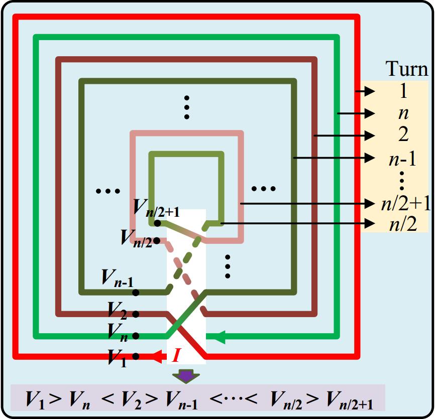
Figure 1.
Schematic diagram of alternating winding of inner and outer turns.
Figure 2a presents the equivalent circuit diagram based on the proposed ITAP method, where Lii (i = 1, 2, ..., n) denotes the self-inductance of the i-th turn, while Mij and kij represent the mutual inductance and coupling coefficient between the i-th and j-th turns, respectively. This methodology effectively reduces the electric field leakage of the system by strategically distributing compensation capacitors across different coil turns. The fundamental configuration involves a fixed compensation capacitor C1 at the first node, which is designed based on two considerations: firstly, this node is located at the outer side of the coil structure, facilitating rapid tuning in practical engineering applications; secondly, this configuration maintains compatibility with classical S-type and LCC-type compensation topologies. The placement of compensation capacitors at remaining nodes is determined through theoretical calculations. The innovation of the ITAP method lies in its design that achieves alternating high-low voltage distribution characteristics between adjacent nodes, as illustrated in Fig. 2b.
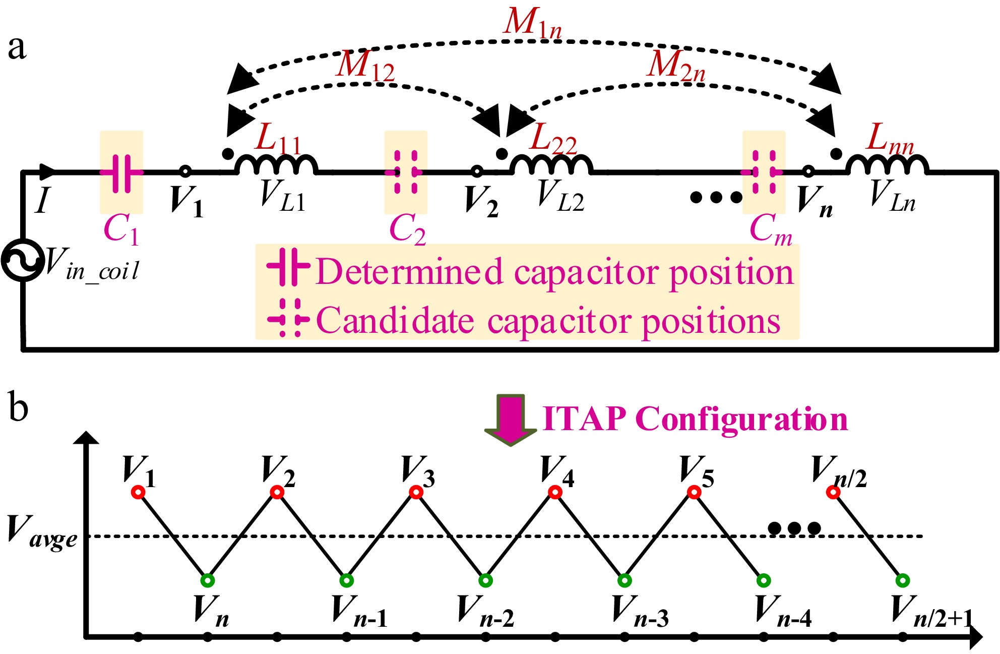
Figure 2.
Equivalent circuit of coil structure. (a) Equivalent circuit diagram. (b) Node voltage distribution diagram of the proposed method.
To determine the optimal placement of compensation capacitors, it is necessary to first obtain the voltage at each node k. Given the presence of mutual inductance between every pair of turns, the coupled inductors in Fig. 2a must be decoupled. Since all inductors are connected in series with additive mutual coupling polarity, the superposition method can be directly applied to compute the equivalent inductance. Specifically, the equivalent inductance Li of each inductor is equal to its self-inductance plus the sum of all relevant mutual inductances:
$ {L_i} = {L_{ii}} + {k_{ij}}\sqrt {{L_{ii}}{L_{jj}}} {\text{ }}i \ne j $ (1) It should be noted that the proposed method does not place compensation capacitors at every node; thus, the total number of capacitors m must be less than the number of turns n. Let mk denote the number of capacitors located between node k and node n (where k corresponds to the node under analysis for voltage Vk), satisfying 0 ≤ mk ≤ m. Neglecting the internal resistance of the inductors, the voltage Vk at node k equals the difference between the total inductive voltage drop and the total capacitive voltage rise across the section from node k to node n, expressed as:
$ {V_k} = {\text{ }}j\omega I\sum\limits_{i = 1}^{n + 1 - k} {{L_{n + 1 - i}}} - j\dfrac{I}{{\omega C}}{m_k} $ (2) Consider m compensation capacitors positioned at locations Si (where Si ∈ {2, 3, ..., n} and i ∈ {1, 2, ..., m}). It should be noted that the first capacitor is fixed at the coil input port (S1 = 1). Consequently, the average node-to-ground voltage can be expressed as the algebraic sum of all equivalent inductive voltage drops minus the total capacitive voltage rises, divided by the total number of nodes n, as given by:
$ {V_{avg}} = \dfrac{{j\omega I\sum\limits_{i = 1}^n {i{L_{n + 1 - i}}} - j\dfrac{{\left( {\sum\limits_{i = 2}^m {{S_i}} - m + 1} \right)I}}{{\omega C}}{\text{ }}}}{n} $ (3) As illustrated in Fig. 2b, the essence of the ITAP method lies in achieving an alternating high-low voltage distribution between adjacent turns, rather than a monotonically decreasing pattern. Specifically, the voltage at high-potential nodes must exceed the average voltage, while that at low-potential nodes remains below the average voltage. Consequently, the classification of nodes into high or low-potential categories can be determined by evaluating the sign (positive or negative) of the deviation between each node voltage and the average voltage. Based on Eqs (2) and (3), the difference between the voltage of each node and the average voltage can be obtained. Its specific expression is given as:
$ {V_{k,diff}} = j\omega I\sum\limits_{i = 1}^{n + 1 - k} {{L_{n + 1 - i}}} - j\dfrac{I}{{\omega C}}{m_k} - j\dfrac{{\omega I\sum\limits_{i = 1}^n {i{L_{n + 1 - i}}} - \dfrac{{\left( {\sum\limits_{i = 2}^m {{S_i}} - m + 1} \right)I}}{{\omega C}}{\text{ }}}}{n} $ (4) To effectively mitigate the electric field leakage induced by inter-turn voltages, it is essential to ensure that the voltage differences between adjacent nodes maintain opposite phases. When the total number of coil turns is odd, one turn will inevitably remain unpaired in the cancellation process. Considering that the innermost turn possesses the following characteristics: (1) it is the farthest from the coupling structure (with electric field attenuation following a 1/r² relationship), and (2) it has the smallest geometric dimensions (resulting in the lowest equivalent voltage division), this letter intentionally excludes it from the cancellation process. This strategy not only ensures system effectiveness but also simplifies the design, as demonstrated by the integer range of k in Eq. (5).
$ \left\{ \begin{array}{l} {Im} \left( {{V_{k,diff}}} \right) \gt 0{\text{, }} k \in \left[ {{\text{1,}}\dfrac{n}{2}} \right] \\ {Im} \left( {{V_{k,diff}}} \right) \lt 0{\text{, }} k \in \left( {\dfrac{n}{2} + \left( {n{\text{ }}\text{mod} {\text{ }}2} \right),n} \right] \\ \end{array} \right. $ (5) Based on Eqs (4) and (5), the positions of all compensation capacitors can be determined using the following expression:
$ \left\{ \begin{array}{l} \sum\limits_{i = 2}^m {{S_i}} \gt A + n{m_k}{\text{, }} k \in \left[ {{\text{1,}}\dfrac{n}{2}} \right] \\ \sum\limits_{i = 2}^m {{S_i}} \lt A + n{m_k}{\text{, }} k \in \left( {\dfrac{n}{2} + \left( {n{\text{ }}\text{mod} {\text{ }}2} \right),n} \right] \\ \end{array} \right. $ (6) where,
$ A = {\omega ^2}C\sum\limits_{i = 1}^n {i{L_{n + 1 - i}}} - n{\omega ^2}C\sum\limits_{i = 1}^{n + 1 - k} {{L_{n + 1 - i}}} + m - 1 $ (7) From Eqs (6) and (7), it can be observed that the placement of compensation capacitors are determined not only by the number of capacitors but also by the coil turns, equivalent inductance, as well as the frequency and amplitude of the AC excitation signal. However, these parameters can typically be predetermined according to the rated power and operating frequency requirements. Therefore, once the coil configuration is fixed, the capacitor positions depend exclusively on the number of compensation capacitors. Furthermore, this method has strong adaptability and can be effectively applied to various compensation topologies connected in series with coils, including the traditional S-type, LCL, and LCC-type compensation networks.
According to the above derivation process, the derivation process of compensating capacitor position can be obtained as follows in Fig. 3. First, system parameters such as output power, switching frequency, input voltage, and the number of capacitors are defined. Based on power transmission requirements, operating frequency, coupling dimensions, and compensation network topology, the coil's self-inductance and number of turns are determined. Using Ansys finite element simulation software, the self-inductance Lii and mutual inductance Mij are extracted. The equivalent inductance Li for each coil segment is then calculated. The capacitor positions are treated as free parameters and optimized iteratively to ensure opposite-phase voltages between adjacent turns for inter-turn voltage cancellation. Finally, optimization results are validated through electric field simulations and experimental testing to confirm the design's effectiveness.
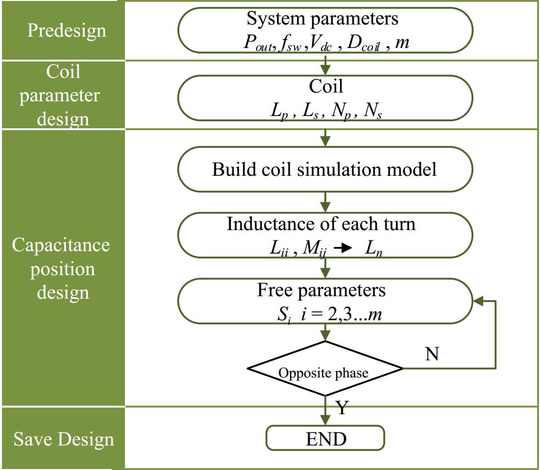
Figure 3.
Capacitor placement design procedure.
The system model with double-side LCC topology
-
The system architecture based on the Interleaved Winding Coil with the ITAP method proposed in this letter is shown in Fig. 4, which employs a double-sided LCC compensation network with bidirectional energy transfer characteristics. Taking the primary side as an example, the series compensation capacitor in the conventional LCC compensation network is divided into a series combination of four sub-capacitors (Cp1−Cp4). Among them, Cp2, Cp3, and Cp4 are integrated into the transmitter coil windings, collectively participating in resonance.
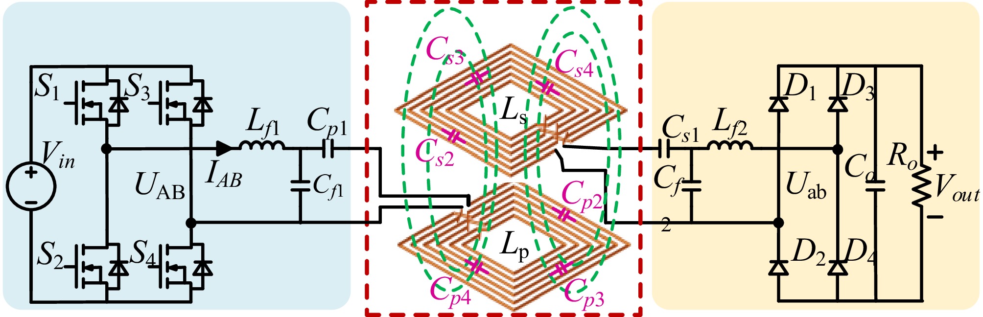
Figure 4.
Structural diagram of the interleaved winding coil system used in the ITAP method system.
The output power of the system can be derived using the fundamental harmonic approximation (FHA) method as[11]:
$ {P_{out}} = \dfrac{{\sqrt {{L_P}{L_S}} }}{{{\omega _0} \times {L_{f1}} \times {L_{f2}}}} \times {k_{coeff}} \times {U_{AB}} \times {U_{ab}} $ (8) where, Lp and Ls are the self-inductances of the primary and secondary coils, respectively, kcoeff is the coupling coefficient, UAB and Uab are the voltages at the inverter and rectifier bridge arms, and ω0 is the system's angular switching frequency.
-
Finite element simulation software HFSS was used to verify the proposed ITAP method, and the specific parameters are shown in Table 1. In the simulation setup, the switching frequency was set to 85 kHz, the coil consisted of 22 turns, and the transmitting and receiving side coil currents were 11.5 and 13 A, respectively. Based on the proposed compensation capacitor placement design process, iterative computations were performed to determine the optimal positions of the compensation capacitors, S1−S4, which were ultimately identified as 1, 9, 16, and 19, respectively.
Table 1. Coil setup parameters.
Parameters Values Two-side coil currents 11.5 A/13 A Resonant frequency 85 kHz Shielding plate dimension 500 mm × 500 mm × 2 mm Ferrite core dimension 460 mm × 460 mm × 5 mm Coil dimension 400 mm × 400 mm × 2.5 mm Number of turns 22 turns Coil inductance 336.4 μH Cpi, Csi, i = 1, 2, 3, 4 45.6 nF Non-segmented capacitor value Cp 11.4 nF In both simulation and experiment, since the transmitter and receiver coils are identical in physical dimensions, number of turns, and compensation capacitor placement, the illustrations primarily feature the transmitter coil for clarity. Figure 5a, b presents the simulated 3D model and the top view of the transmitting coil, respectively. In Fig. 5b, the capacitor model employs the Lump RLC boundary condition in HFSS to emulate actual capacitive components, where specific capacitance values are assigned to simulate the capacitive effect. Under identical operating conditions, the proposed compensation capacitor placement is compared with average segmented compensation (S1−S4 located at 1, 7, 12, and 18, respectively) with non-segmented compensation. The magnetic and electric field distributions for the three compensation schemes are shown in Fig. 5c. The comparison results indicate that the magnetic field distributions are almost identical across the three schemes, demonstrating that the placement of compensation capacitors has no significant impact on the magnetic field distribution of the coupling mechanism, and thus does not notably affect the system's transmission efficiency. Regarding electric field distribution, by the IEEE C95.1TM-2019 standard, the permissible exposure limit for human exposure to electric fields in the 3 kHz–100 kHz frequency range is 614 V/m. Simulation results demonstrate that the proposed ITAP configuration not only ensures complete compliance with safety standards for the external electric fields of the coupling mechanism but also effectively confines high-field regions to the vicinity of the coils, thereby significantly reducing EMI interference with surrounding equipment.
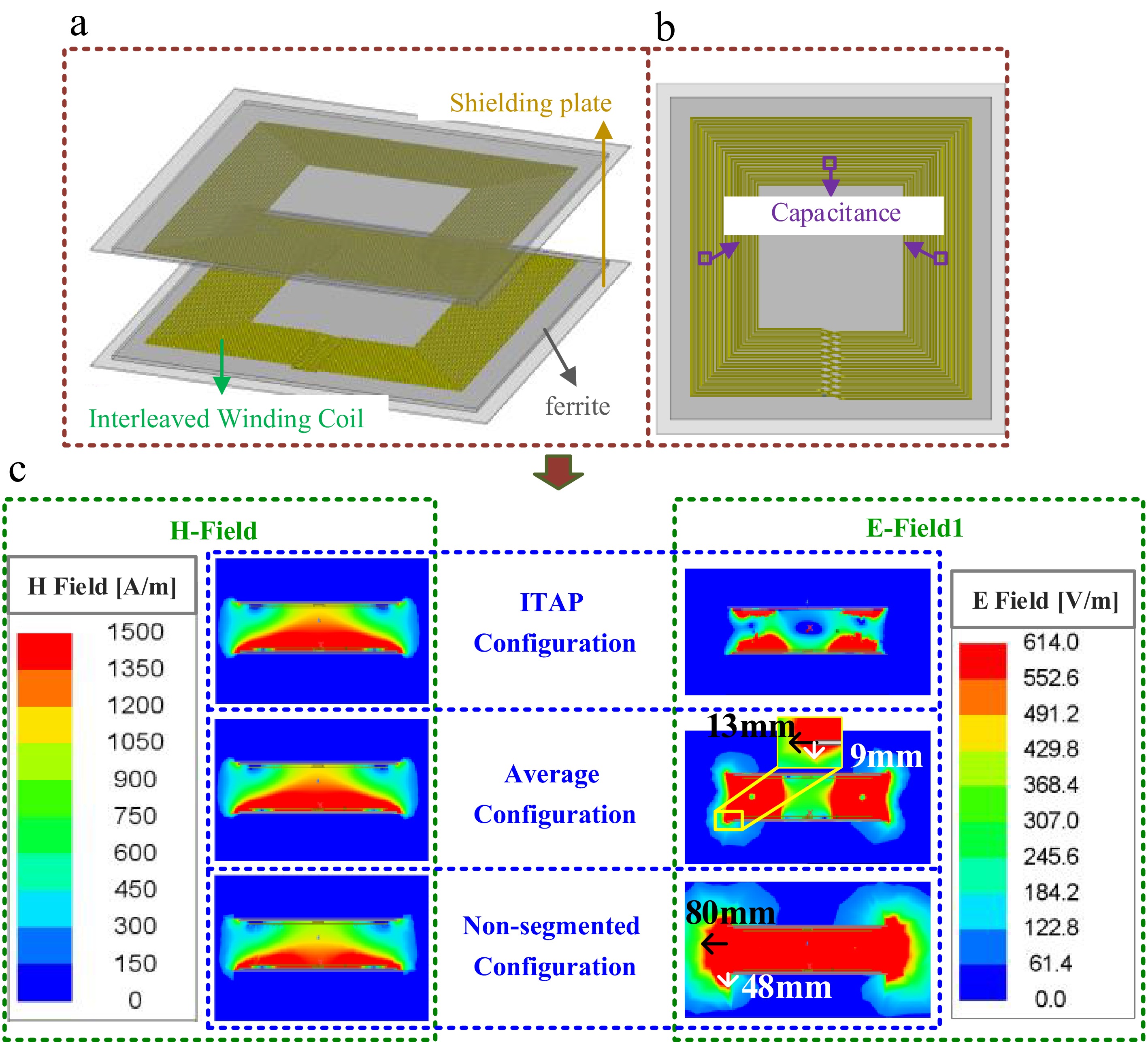
Figure 5.
(a) 3D simulation model of ITAP coil structure. (b) Top view of the transmitting coil and the position of the compensation capacitor. (c) Magnetic and electric field distribution.
To validate the advantages of the proposed ITAP method in reducing electric field exposure, a 3.3 kW prototype was constructed. The experimental setup is shown in Fig. 6, where the coil structure with an ITAP configuration and the compensating capacitor are located in the upper right corner of the figure. The positions of the three thin-film compensating capacitors in the diagram correspond to those of the capacitors in Fig. 5b. The inverter employs Infineon's IMZ120R030M SiC MOSFET (1,200 V/30 mΩ) as the switching transistor.
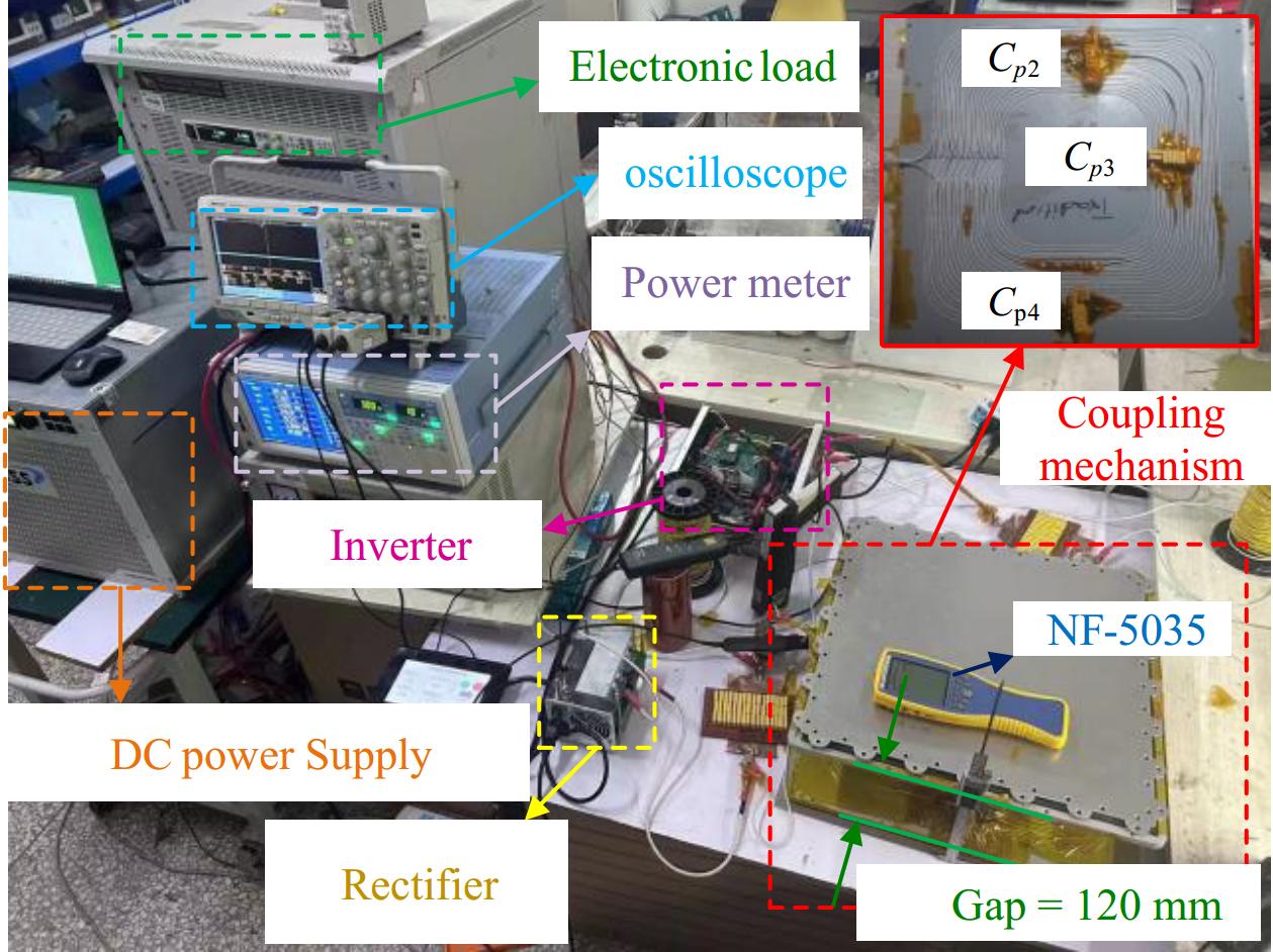
Figure 6.
Experimental setup.
Figure 7a shows the current and voltage waveforms of the system during operation measured by the MDO3024 oscilloscope, where Ipri is the current of the transmitting coil. Since the waveforms of the three compensation configurations are nearly identical, only the experimental waveform for the ITAP configuration is presented. It can be observed that the system successfully achieves zero-voltage switching (ZVS). Figure 7b presents the DC-DC efficiency curves for the three configurations at different output power levels measured by the WT1800 power analyzer. It can be observed that the proposed ITAP method does not affect the system's transmission efficiency, further validating the accuracy of the simulation results.
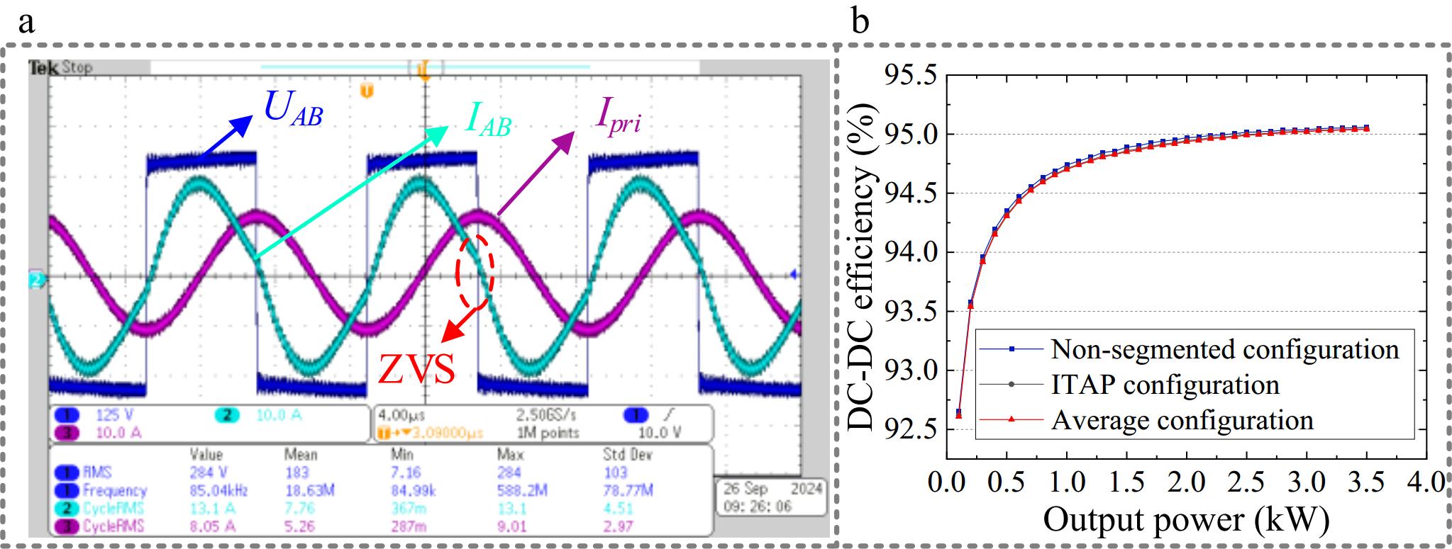
Figure 7.
The operating waveform of the ITAP system and the efficiency comparison curves.
Electric field intensity measurements for the three configurations (ITAP, non-segmented configuration, and average configuration) were conducted using an NF-5035 tester. The measurements were initiated at the mid-height position of the outer edge of the coupling mechanism and performed point-by-point, moving outward in 5 cm increments, as illustrated in Fig. 8a. The test results are presented in Fig. 8b. The data reveal that the electric field intensity of the ITAP configuration is only 50.93% of the non-segmented configuration and 62.73% of the average configuration. These results demonstrate that the ITAP configuration significantly reduces electric field exposure levels.
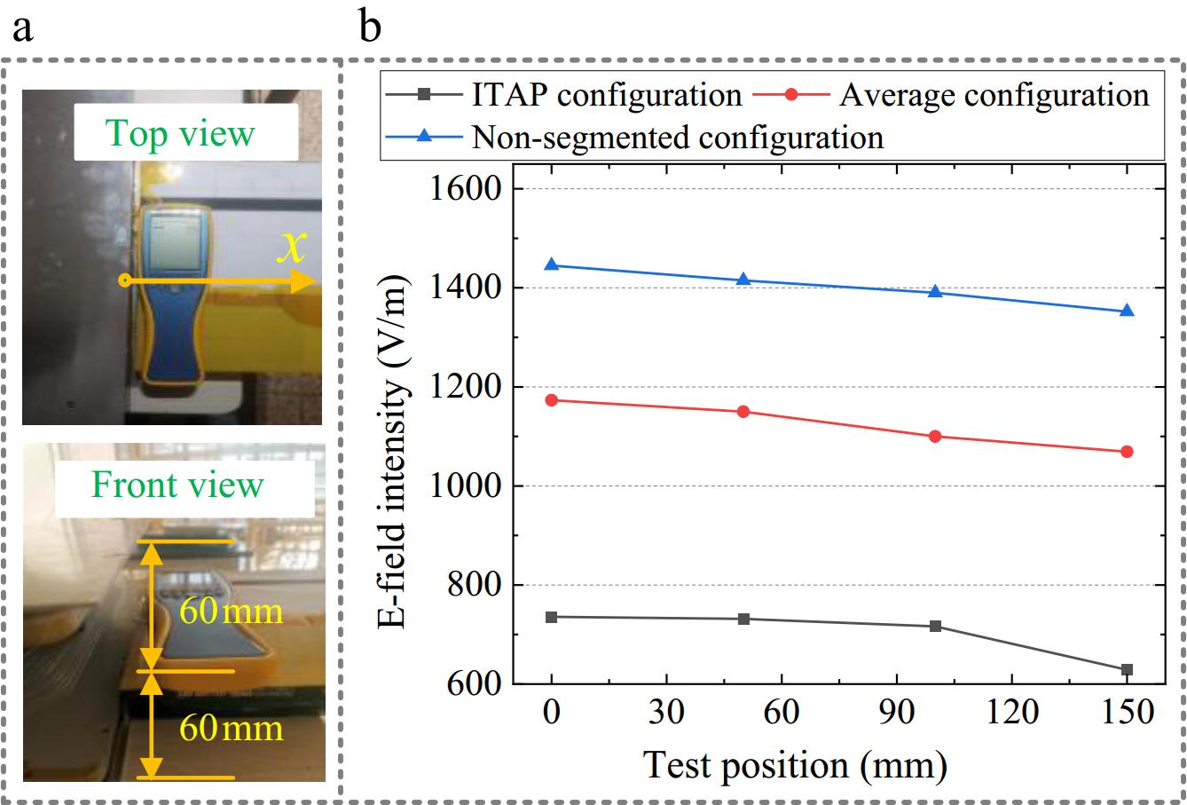
Figure 8.
The variation of transmission efficiency with output power.
-
Although the proposed method for ITAP demonstrates good adaptability in bilateral LCC systems, its application still has certain limitations. Firstly, in terms of applicable topologies, this method is only suitable for compensation structures where capacitors are connected in series with coils (e.g., S-type, LCL-type, LCC-type). For parallel compensation networks (such as P-type topologies), the parallel characteristics of capacitors and coils make segmented compensation unattainable, rendering this method difficult to directly extend to such topologies. Secondly, in addition to requiring predefined basic parameters such as operating frequency, number of coil turns, and compensation capacitance values, it is also necessary to obtain the self-inductance of each coil turn and the mutual inductance between turns through theoretical analysis or simulation, which increases the computational burden of the system. Future research could explore adaptive correction mechanisms for compensation capacitance to reduce reliance on the self-inductance and mutual inductance parameters of each coil turn. It is also possible to conduct a deeper exploration of the ITAP method, starting from different coil sizes and frequency parameters, and carry out optimization research for the application requirements of multiple scenarios.
-
This letter presents a novel interleaved winding coil and the ITAP method aimed at reducing the electric field emissions in IPT systems. The proposed ITAP method strategically places segmented compensation capacitors to create opposing phase voltage differences between adjacent turns of the coil. This approach maximizes the cancellation of inter-turn voltages, significantly reducing both internal and external electric field intensities. Simulation and experimental results validate the effectiveness of this design, showing that it substantially lowers electric field exposure without compromising the efficiency of wireless power transfer. The comparison with traditional average segmented and non-segmented compensation methods demonstrates the ITAP method's superior ability to mitigate high electric field regions, enhancing the safety of the system.
This work was supported in part by the National Natural Science Foundation of China (Grant No. 52467023), and in part by Yunnan Fundamental Research Project (Grant No. 202201AT070155).
-
The authors confirm contribution to the letter as follows: conceptualization, resources, funding acquisition, writing-original draft preparation, writing-review and editing: Li Z, Shafiq Z, Liu Z; methodology, data curation: Shafiq Z; software: Shafiq Z, Li T; validation: Li Z, Rong E; formal analysis: Liu Z, Lu S; investigation, project administration: Li Z; supervision: Li S. All authors have read and agreed to the final version of the manuscript.
-
All data included in this study are available upon reasonable request by contacting the corresponding author.
-
The authors declare that they have no conflict of interest.
- Copyright: © 2025 by the author(s). Published by Maximum Academic Press, Fayetteville, GA. This article is an open access article distributed under Creative Commons Attribution License (CC BY 4.0), visit https://creativecommons.org/licenses/by/4.0/.
-
About this article
Cite this article
Shafiq Z, Li S, Liu Z, Lu S, Li T, et al. 2025. Mitigating leakage electric field in inductive power transfer via winding and compensation capacitor configuration. Wireless Power Transfer 12: e028 doi: 10.48130/wpt-0025-0023 

Mitigating leakage electric field in inductive power transfer via winding and compensation capacitor configuration
- Received: 09 February 2025
- Revised: 21 June 2025
- Accepted: 04 July 2025
- Published online: 22 October 2025
Abstract: As inductive power transfer (IPT) systems gain increasing attention, optimizing electric field distribution and reducing intensity are crucial to ensuring system safety within electromagnetic exposure limits. This letter addresses the issue of high electric field intensity by introducing a novel interleaved winding configuration. An Inter-Turn Anti-Phase (ITAP) method is also proposed to adjust the placement of distributed compensation capacitors, ensuring that the potential between adjacent turns exhibits opposite-phase characteristics. This adjustment maximizes the cancellation of the inter-turn electric field, effectively reducing the electric field intensity both within the coil gap and in the external environment. Finite element simulations and experimental validation on a 3.3 kW prototype demonstrate that, without observable changes in power transfer characteristics or efficiency, the proposed approach reduces leakage electric field intensity by approximately 40% compared to traditional distribution compensation with an average segmentation. When compared to non-segmented compensation methods, the reduction is around 50%. These results highlight the effectiveness of the proposed method in lowering electric field exposure levels and enhancing the safety of IPT systems.