


-
The magnetic coupling resonance wireless power transfer (MCR-WPT) system is considered an effective solution for wireless power transfer (WPT) systems with power levels of hundreds of watts, kilowatts, or even higher due to its advantages of long transmission distance, high transmission power level, and high system efficiency[1]. Soft magnetic materials represented by Mn-Zn power ferrites are often added as magnetic cores to the magnetic coupler of WPT systems to enhance the performance of magnetic couplers, achieve magnetic concentration, increase coupling coefficients, and thus improve transmission efficiency. However, with the increasing demand for power density and the diverse adjustment of WPT technology application scenarios, the low saturation magnetic flux density, low thermal conductivity, low thermal stability, and mechanical mechanism brittleness of traditional Mn-Zn ferrites are gradually exposed and become potential bottlenecks for the further development of WPT technology.
In recent years, flexible amorphous and nanocrystalline materials, especially Fe-based flexible nanocrystalline materials, have received increasing attention in the application of MCR-WPT systems[2]. Compared with ferrites, nanocrystalline materials have greater flexibility and superior electromagnetic properties in the design of magnetic cores for WPT system magnetic couplers[3]. Fe-based nanocrystalline materials have significant differences in material properties from Mn-Zn ferrite, mainly reflected in high conductivity, high magnetic permeability, and low hysteresis loss. Table 1 shows the comparison of basic parameters of nanocrystalline and Mn-Zn ferrite from two typical manufacturers. Specifically, the displayed nanocrystalline materials are the thin ribbon units that have not undergone fragmentation treatment. Higher conductivity and magnetic permeability enable Fe-based nanocrystalline materials to have better electromagnetic shielding ability and enhanced mutual inductance of magnetic couplers. However, nanocrystalline magnetic cores with high conductivity will generate eddy currents opposite the coil currents in WPT systems, resulting in additional eddy current losses. Therefore, it is necessary to model and calculate the shielding efficiency and additional eddy current losses of Fe-based nanocrystalline magnetic core couplers to evaluate the application requirements of nanocrystalline materials in WPT systems.
Table 1. Comparison of basic parameters between typical Fe-based nanocrystalline and Mn-Zn ferrite materials.
Symbol Parameter Fe-based Nanocrystalline @ YuNeng Tec u106 Mn-Zn Ferrite @ TDK PC95 Bs (T) @ 25 °C & H = 1,194 A/m Saturation magnetic induction 1.25 0.53 $\mu_0$ (Gs/Oe) Initial permeability 100,000 3,300 $\mu_{\max} $ (Gs/Oe) Maximum magnetic permeability 1,000,000 6,000 Hc (A/m) @ 25 °C&H = 1,194 A/m Coercivity 1.60 9.5 Tc (°C) Curie temperature 570 215 ρD (kg/m3) Bulk density 7,200 4,900 PLoss (kW/m3) @ 100 kHz & 25 °C & 0.2 T Core loss 250 350 PLoss (kW/m3) @ 100 kHz & 100 °C & 0.2 T Core loss 180 290 ρR (Ω·m) Volume resistivity 1.1 × 10⁻⁶ 6 From the perspective of material properties and nanocrystalline applications, compared to ferrites, flexible nanocrystalline materials exhibit higher relative permeability and maximum saturation flux density, enabling electromagnetic gain and shielding while effectively avoiding magnetic saturation issues in the core region of magnetic coupling resonance wireless power transfer technology. Currently, one of the most prominent applications of nanocrystalline materials in WPT technology is in electric vehicle magnetic couplers, as exemplified by the SAE-J2954 standard, where they are paired with DD coils to enhance transmission efficiency[4−7]. Leveraging the unique flexibility and mechanical deformation resistance of nanocrystalline materials, recent research has increasingly applied them to WPT systems with special-shaped enclosures, such as submersibles and drones, achieving excellent conformability, lightweight design, and integration[8−15]. Additionally, in WPT compensation network inductors, nanocrystalline ribbons and rings have become a key improvement measure for reducing parasitic internal resistance losses[16,17].
From the perspective of material structure applications, existing research has primarily developed two typical approaches. On the one hand, composite magnetic shielding structures can be created using two or more magnetic materials combined with shielding materials to improve shielding efficiency[18−20]. On the other hand, optimized magnetic structures using the same nanocrystalline material can be employed to enhance specific magnetic properties of traditional magnetic structures[21−23].
From the standpoint of magnetic coupler modeling, the precise analytical modeling of magnetic couplers remains a critical and hot topic in WPT technology. Accurate modeling of WPT magnetic couplers allows for the determination of system coupling performance, coil resistance, self-inductance, and coupling coefficients during the early design phase without relying on finite element software. This is highly beneficial for quickly assessing whether the design parameters of the magnetic coupler meet expectations during the initial design stages. Current research primarily focuses on the development of analytical models for coreless, infinitely large core, and finite-sized core configurations[24,25]. Many studies have adopted approaches similar to laminated silicon steel modeling to analyze the anisotropy of nanocrystalline cores in thin ribbon laminations[26]. However, few studies have addressed the modeling of multilayer shielding efficiency and eddy current losses.
However, current research on the application of Fe-based flexible nanocrystalline ribbons primarily focuses on addressing the inherent limitations of traditional ferrites in terms of magnetic properties and mechanical structures. Most studies have concentrated on the straightforward substitution of magnetic core materials in couplers, with limited attention dedicated to the modeling and magnetic circuit analysis of laminated flexible nanocrystalline materials specifically for WPT system applications. To address the limitations of traditional power ferrites in improving the power density of WPT systems and overcoming their mechanical brittleness, and to tackle the current challenges of parasitic eddy current losses and associated thermal imbalance issues in WPT nanocrystalline materials, this study proposes to conduct research from the perspectives of magnetic material design and magnetic structure optimization. The main contributions of this paper are as follows:
(1) A comprehensive evaluation was conducted on the application requirements of magnetic materials and magnetic structures for the magnetic coupler of high-efficiency and high-power density WPT systems, and the process characteristics and general application methods of Fe-based flexible nanocrystalline ribbon magnetic materials were summarized.
(2) A general modeling method for Fe-based flexible laminated ribbon nanocrystalline magnetic core structure was proposed, and the modeling and analytical calculation of its shielding energy efficiency and additional eddy current loss were completed.
(3) A hybrid multi-permeability nanocrystalline magnetic core structure was proposed for typical unipolar WPT magnetic couplers. After optimizing the design with multi-objective conditions using finite element and analytical methods, the novel structure achieves better coupling performance, shielding energy efficiency, and thermal characteristics compared to the traditional flat laminated structure.
(4) A 3 kW unipolar WPT system experimental testing platform was designed and built, while comprehensively tested and compared the proposed magnetic structure with five traditional ferrite and nanocrystalline structures, verifying the superiority of the proposed substructure.
-
Soft magnetic materials have high magnetic permeability electromagnetic properties, which can effectively concentrate and guide magnetic fields, achieve spatial reshaping of magnetic flux, and improve the magnetic circuit distribution of the surrounding environment of the material. High-performance magnetic materials, such as magnetic core structures integrated into wireless energy transmission magnetic couplers, can effectively improve the quality factor and mutual inductance coupling coefficient of coils, which is crucial in improving system power levels and output efficiency. In addition, the beam and aggregation effects of magnetic materials can effectively improve the electromagnetic leakage of magnetic couplers, reduce the electromagnetic radiation interference of wireless energy transmission coils on power electronic devices and the surrounding environment, and achieve electromagnetic compatibility design and electromagnetic shielding effect of the system[27,28]. Generally, for the application of magnetic couplers in WPT systems, more stringent design requirements are required for the magnetic materials and structures used, which can be considered from the following perspectives.
Efficient and high power density
-
The application objects of WPT systems usually have limited load capacity, so it is necessary to provide the highest possible power density and transmission efficiency. For magnetic core design, on the one hand, it is necessary to use magnetic materials with high permeability and low conductivity to achieve high coupling characteristics while minimizing the additional eddy current losses caused by parasitic internal resistance to choose the highest saturation magnetic flux density possible to avoid magnetic saturation. On the other hand, the design of magnetic structures should also be optimized based on the optimal direction for achieving magnetic circuit closure, utilizing the deformability of magnetic materials to achieve magnetic aggregation and constraint design, and enhancing the coupling capability of magnetic couplers.
System thermal stability and electromagnetic compatibility
-
In addition to the WPT system, electric carriers also integrate a large number of electrical components, which place high demands on their internal thermal stability and electromagnetic compatibility. The magnetic core of the magnetic coupler should achieve as little heat generation as possible, and the magnetic structure should achieve a good electromagnetic shielding effect to ensure the reliability of the electromagnetic compatibility design of the internal electrical system of the power carrier.
Structural conformance and system integration
-
Taking unmanned underwater vehicles as an example, modern unmanned equipment usually has irregular mechanical shell shapes and narrower installation spaces compared to electric vehicle chassis, which requires the strict design of magnetic couplers, including coils and magnetic cores, from the aspects of conformity and integration. Conformal deformation is primarily evident in the assembly of the magnetic coupler, ensuring that it does not compromise the structural and mechanical properties of the carrier. Therefore, the magnetic core must possess a certain degree of bendability and flexibility. Additionally, due to the limited installation space within the carrier, it is essential to design the magnetic core to be as thin and lightweight as possible, to meet the demands of integrated installation and lightweight design.
Flexible nanocrystalline unit and its fragmentation process characteristics
-
Generally, the thinner the processed nanocrystalline ribbon, the smaller its eddy current loss and the better its transmission performance. The current nanocrystalline ribbon technology can roll materials into 15−30 μm. This article selects Fe-based nanocrystalline ribbon products with a unit profile thickness of 18 μm and a bandwidth of 65mm. The grain fragmentation of nanocrystalline materials can be achieved through heat treatment and mechanical crushing processes. The heat treatment process includes annealing in a nitrogen environment and crystallization of nanocrystalline particles on an amorphous substrate, thereby forming an amorphous nanocrystalline biphasic structure. This biphasic structure has excellent electromagnetic properties. The mechanical crushing process decomposes nanocrystalline alloy materials into a series of small fragmented nanocrystalline particles through a crushing device and rolls them into the precise thin flexible ribbon materials, as shown in Fig. 1.
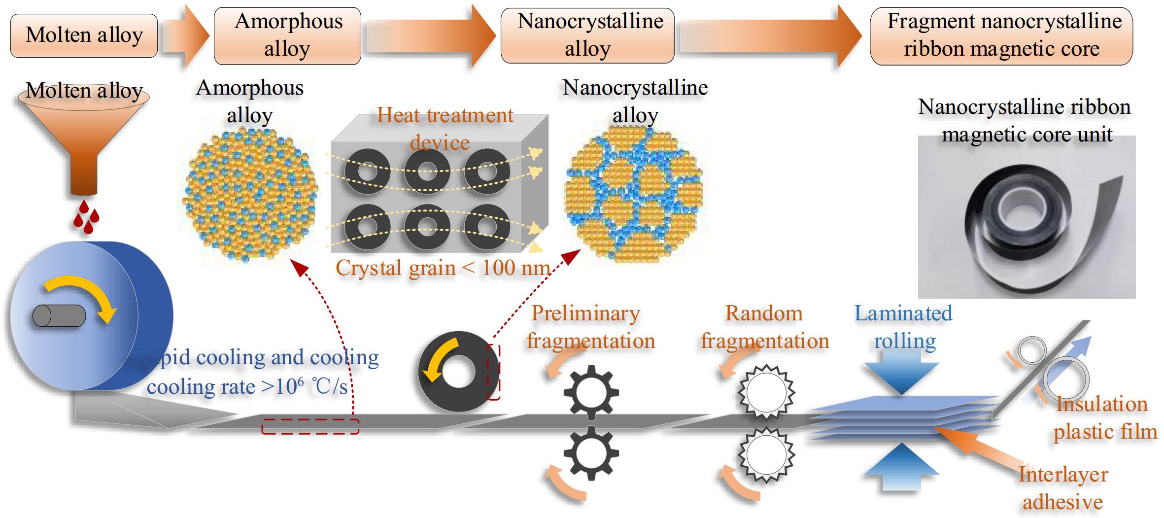
Figure 1.
Schematic diagram of the fragmentation process of nanocrystalline ribbon core.
The nanocrystalline fragmentation process can increase the resistivity of nanocrystalline ribbons by blocking the eddy currents of nanocrystals on the XOY plane, as shown in Fig. 2. After fragmentation, the tiny nanocrystalline particles will form many air gaps, which confine the vortex elements to smaller areas and effectively block them. The finer the grain size, the more significant the eddy current blocking effect and the higher the electrical resistivity.
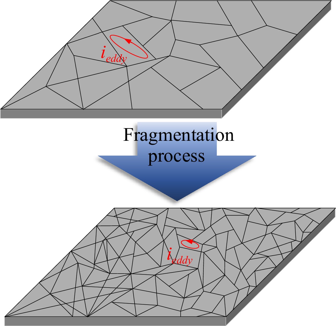
Figure 2.
Schematic diagram of the fragmentation process of nanocrystalline ribbon core.
However, while the fragmentation process increases the resistivity and reduces eddy current losses, it also reduces the magnetic permeability of nanocrystalline materials. As the degree of fragmentation increases, the magnetic permeability of nanocrystals decreases. Due to the establishment of an air gap caused by the demagnetization field, the magnetization of the nanocrystals is hindered, and the saturation magnetic field strength Hm increases. This is beneficial for avoiding the problem of magnetic core saturation caused by the increase of winding current in WPT systems. Still, it may also affect the transmission performance of WPT systems.
The permeability of the nanocrystalline ribbon material will indirectly affect the additional eddy current loss of the core, so it is necessary to determine the lower limit of the relative permeability of the core of the magnetic coupler[29]. As shown in Fig. 3, the fluctuation of self-inductance and coupling coefficient of 200 mm * 200 mm circular magnetic coupler is simulated in ANSYS Maxwell with the change of permeability, which shows that although the high permeability property of the nanocrystalline can better suppress the leakage, it does not significantly improve the coupling. When the relative permeability decreases from 3,000 to 20, the coupling coefficient first decreases slowly, and the slope starts to increase near µ = 600 and then decreases sharply at µ = 400. In addition, although the core greatly reduces the reluctance around the receiver coil, most of the surrounding space is still occupied by air, which causes the coil self-inductance to decrease first gradually and then rapidly with decreasing permeability, similar to the change in the coupling coefficient. Therefore, the improvement of self-inductance, coupling coefficient, and leakage flux of the WPT system by the increase of magnetic permeability when the core permeability is not lower than 600 is not so significant, but the additional eddy current losses induced by the nanocrystalline material still need to be considered.
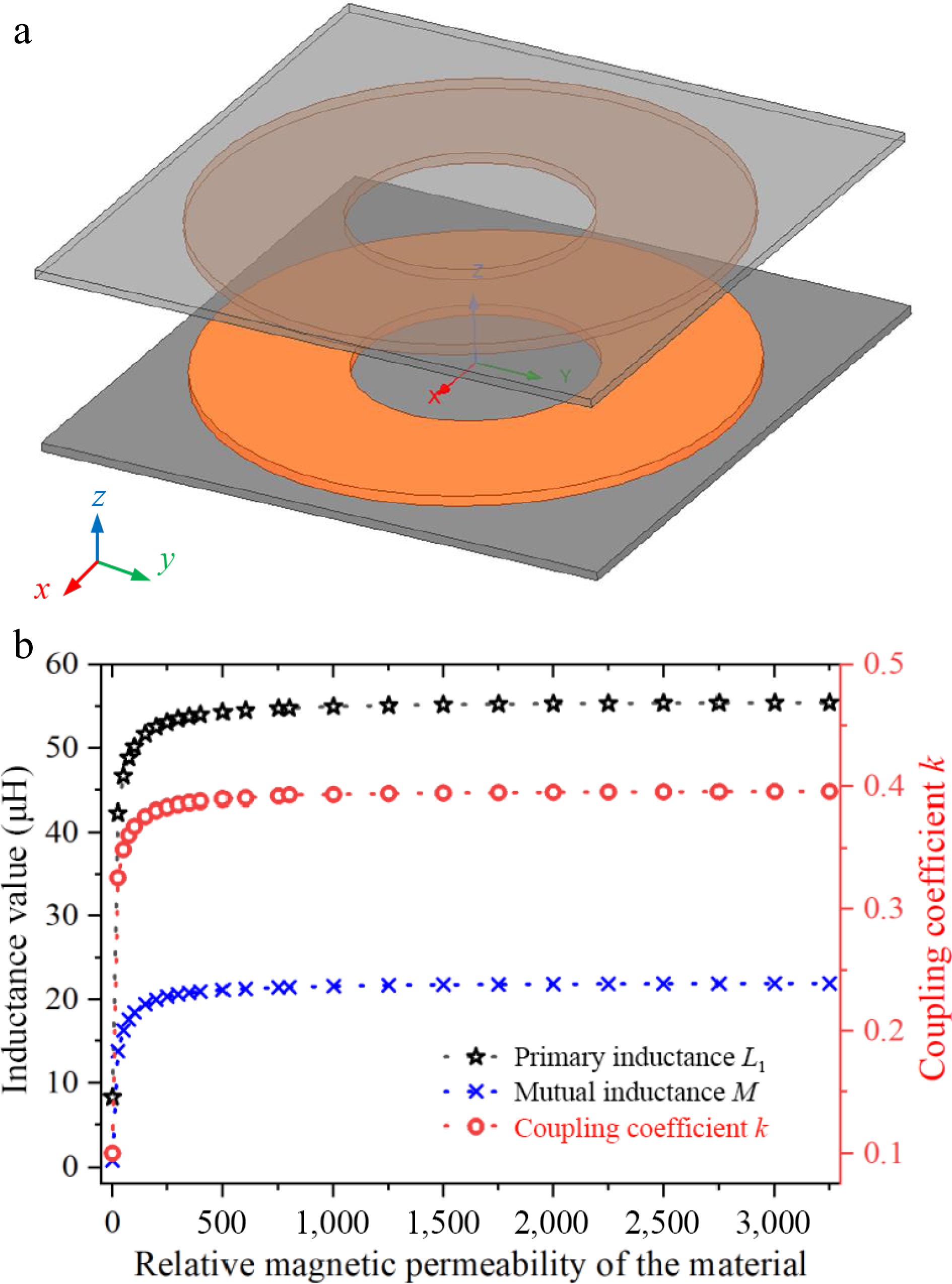
Figure 3.
Simulation results and simulation modeling of the relationship between inductance values, coupling coefficients and relative permeability of materials. (a) Maxwell finite element simulation model. (b) Relationship between inductance, coupling coefficient, and permeability.
Lamination and transmission characteristics analysis of flexible nanocrystalline
-
The magnetic core is typically positioned close to the Litz coil in the WPT system magnetic coupler. To prevent magnetic saturation caused by the ribbon nanocrystals when operating in high-power systems, it is beneficial to use multiple layers of ribbon cores that are rolled and bonded together. This approach enhances the core ability to tolerate higher levels of magnetic flux density before saturation occurs. Figure 4 illustrates the process of laminating a 1-mm-thick nanocrystalline ribbon core. In this design, 18-μm nanocrystalline ribbon units are held in place with a 2-μm adhesive and an insulating film is attached to the exterior of the finished core. The stacked and rolled configuration, along with the application of adhesive, helps to limit eddy currents around the sides of the nanocrystalline ribbon cores. This results in a fragmentation-like effect that confines the eddy currents to a smaller area, thereby reducing additional eddy current losses.
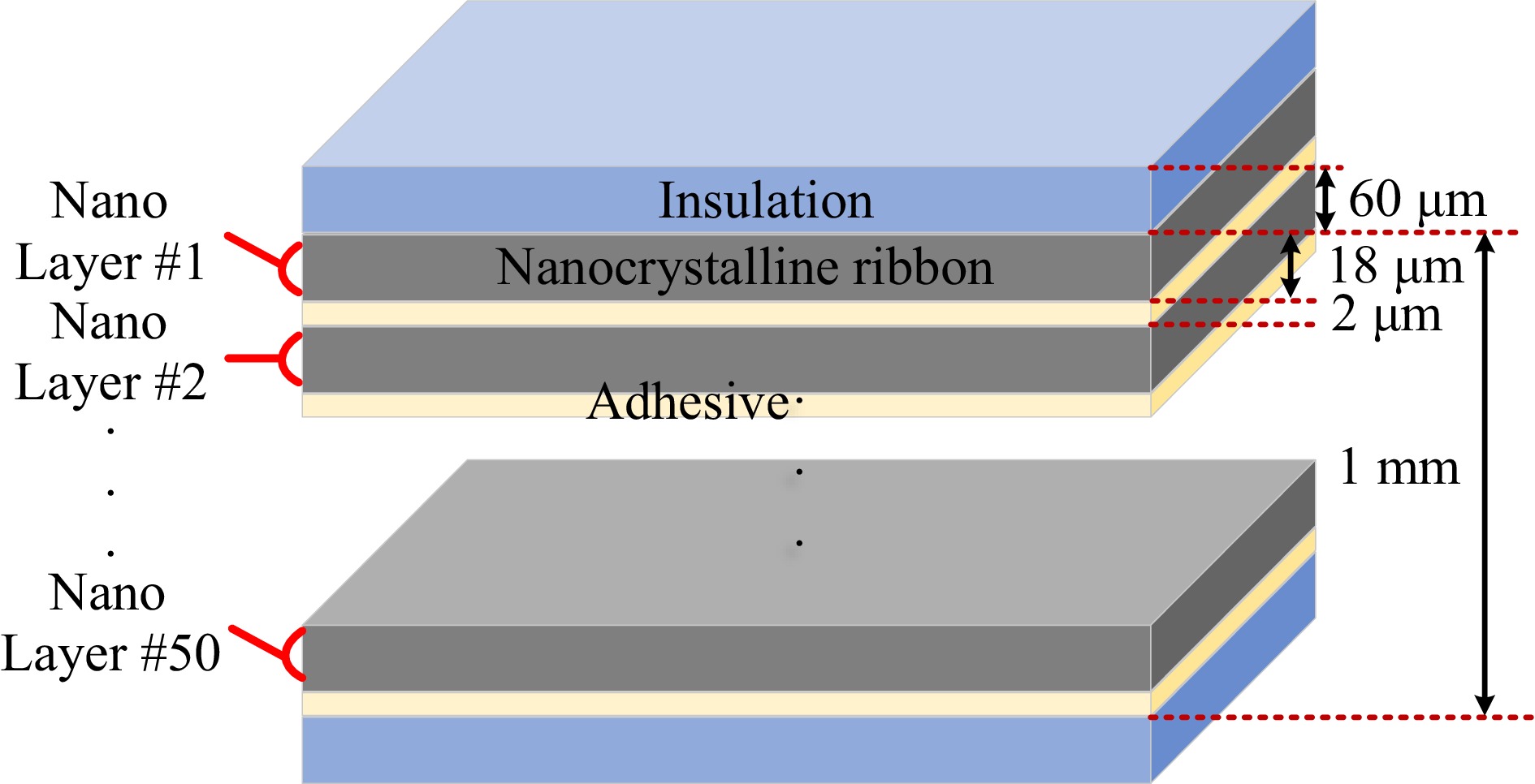
Figure 4.
Schematic diagram of 1 mm thickness laminated nanocrystalline magnetic core structure.
The coil surface of the magnetic coupler is used as the reference plane, and the lamination direction can be either perpendicular or parallel to the reference plane, as shown in Figure 5. The thickness of the nanocrystalline ribbon is tr and the thickness of the adhesive is tad. The nanocrystalline share in the laminated ribbon core can be defined by the lamination factor F, with:
$ F = \dfrac{{{t_{\text{r}}}}}{{{t_{\text{r}}} + {t_{{\text{ad}}}}}} $ (1) 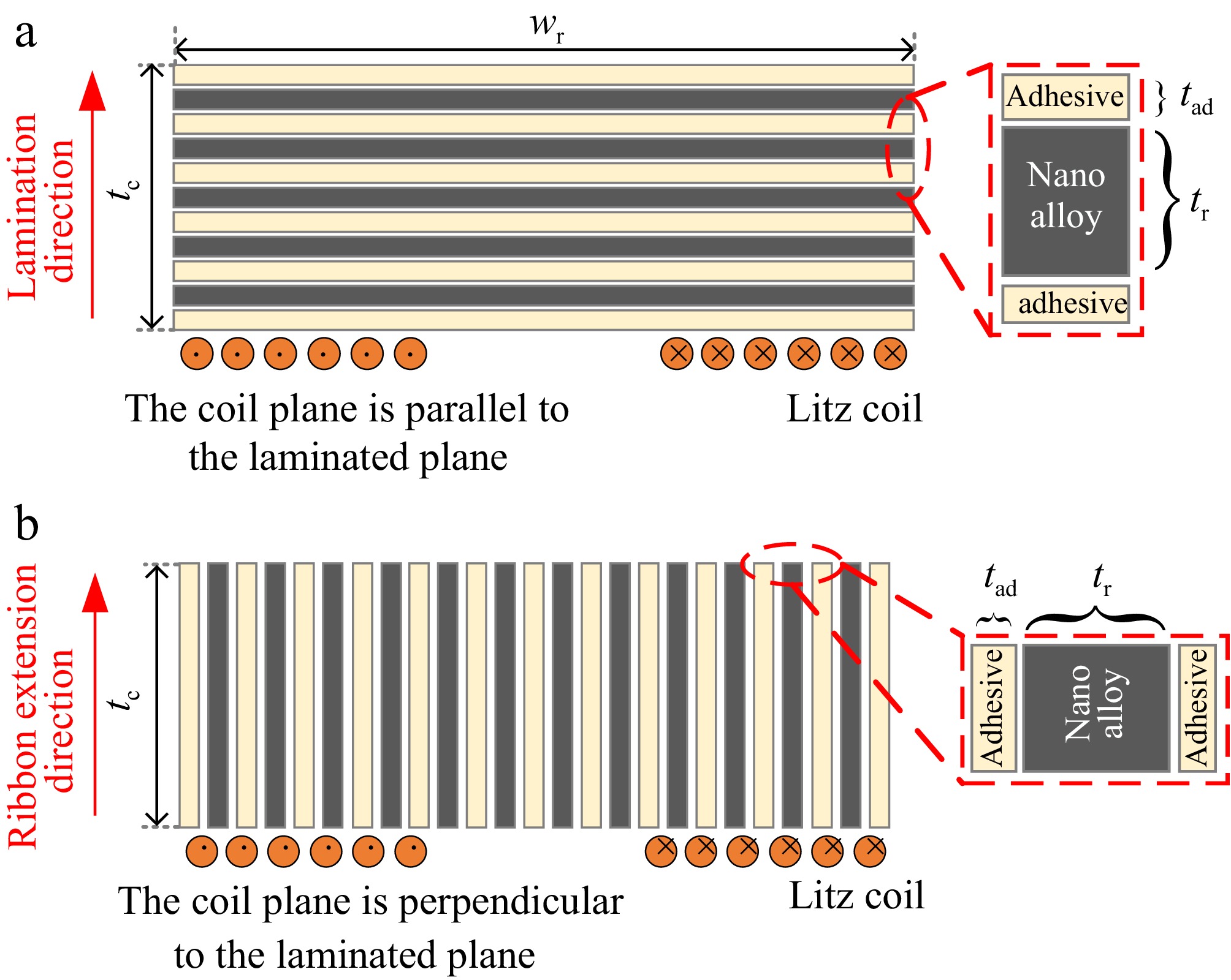
Figure 5.
Two typical lamination process approaches for nanocrystalline ribbons. (a) Flat laminated. (b) Longitudinal laminated.
The commonly used flat and vertical laminated nanocrystalline structures currently do not fully account for the magnetic reluctance distribution in unipolar coil designs. Figure 6 illustrates the application of laminated ribbon nanocrystalline cores in unipolar coils. Specifically, the flat laminated nanocrystalline core structure, while straightforward and easy to implement, considers the distribution of self-coupling paths but weakens the mutual-coupling paths. On the other hand, the vertically laminated nanocrystalline structure facilitates magnetic flux transmission along the cutting direction, making it more suitable for bipolar coil structures, such as the DD coil[5].
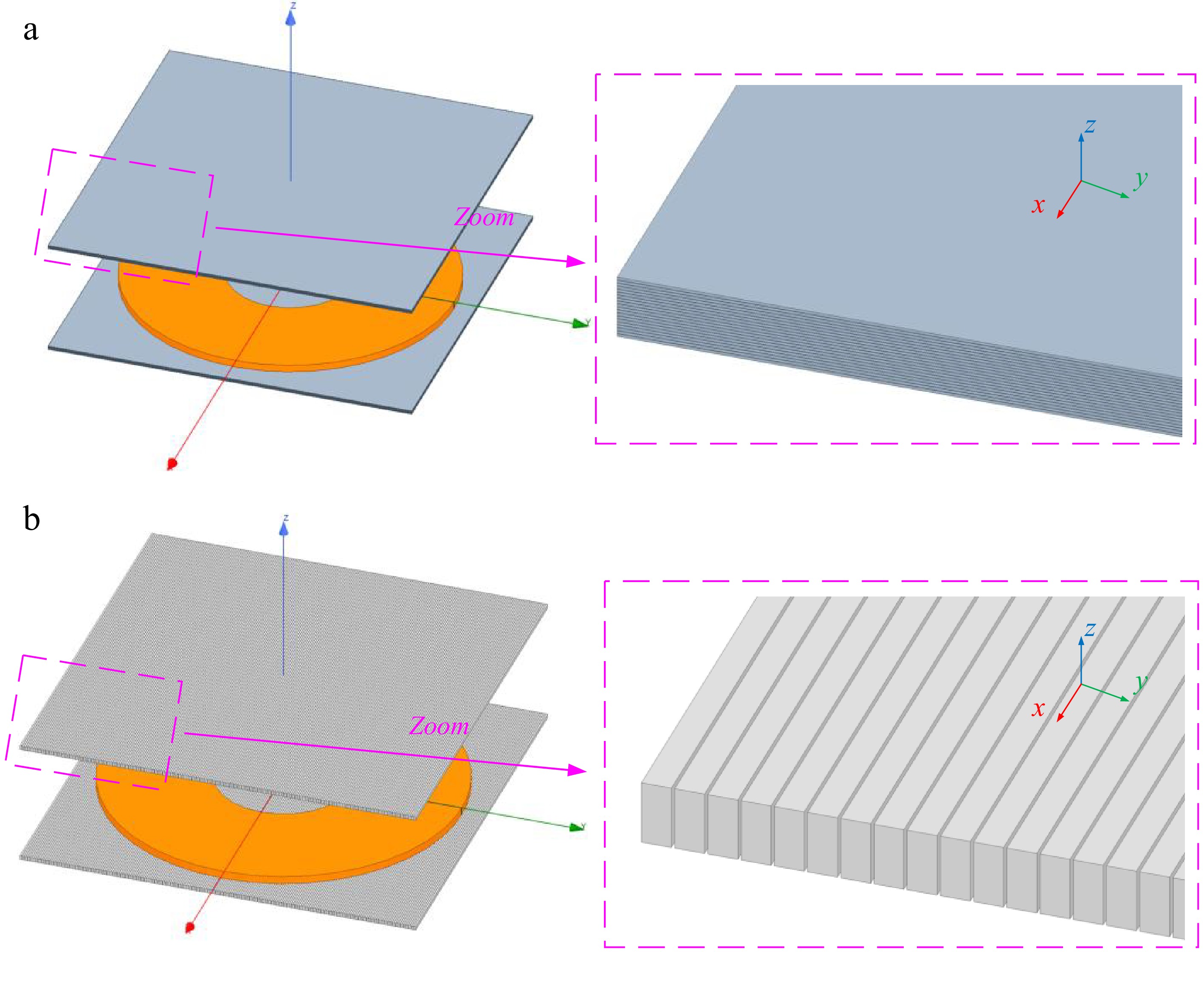
Figure 6.
Schematic diagram of laminated nanocrystalline ribbon core structure applications in unipolar coils. (a) Application of flat-laminated nanocrystalline. (b) Application of vertical-laminated nanocrystalline.
However, due to the electromagnetic properties of nanocrystalline materials with high permeability and high electrical conductivity, the addition of adhesive causes the magnetic path of the core to be cut along the normal direction. In other words, when a flat laminated structure, as shown in Fig. 7, the magnetic core has different electromagnetic properties in the tangential and normal directions. That is, for the inside of the nanocrystalline ribbon material, and the fundamental magnetic properties of the material are isotropic. However, for the lumped nanocrystalline core as a whole after being laminated, the material properties are anisotropic, the permeability and conductivity are different in the normal and tangential directions.
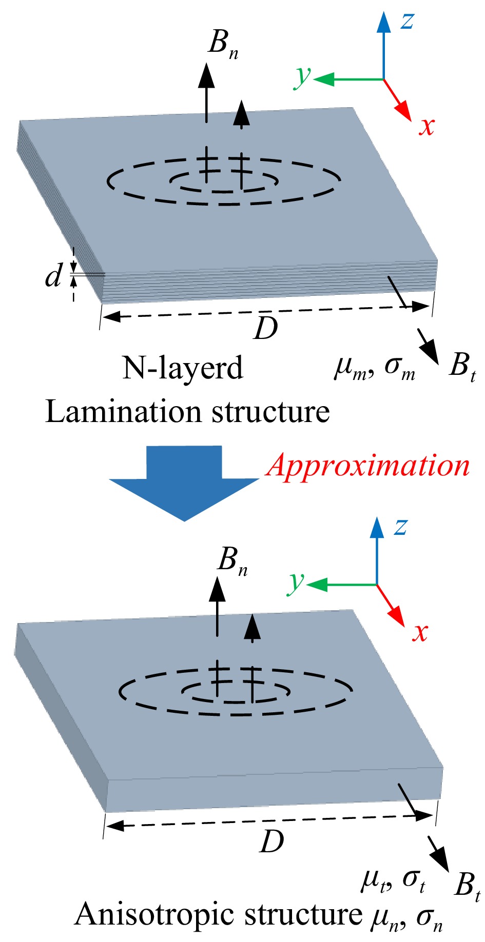
Figure 7.
Magnetic structure approximation by homogenization modeling method.
The Fe-based nanocrystalline ribbon unit possesses magnetic permeability µm and electrical conductivity σm. The equivalent magnetic core can be approximated as a monolithic solid structure under the assumption that the magnetic permeability and electrical conductivity of free space are zero. However, the model captures the anisotropy of the laminated structure by introducing distinct permeability and conductivity parameters, µt, σt, and µn, σn, in the tangential and normal directions, respectively[26]. Based on the uniform medium analysis, the conductivity and permeability parameters of the nanocrystalline core block model in different directions can be calculated using Eqns (2) to (5).
$ {\mu _t} = F{\mu _m} + (1 - F){\mu _0} $ (2) $ {\mu _n} = \dfrac{{{\mu _m}{\mu _0}}}{{F{\mu _0} + (1 - F){\mu _m}}} $ (3) $ {\sigma _t} = F{\sigma _m} $ (4) $ {\sigma _n} \approx {\left( {\dfrac{d}{D}} \right)^2}\dfrac{{{\sigma _m}}}{F} $ (5) where, d and D are the thickness and width of the laminated nanocrystalline ribbon, respectively. At this time, the equivalent skinning depth of the laminated nanocrystalline material is:
$ {\delta _{{\text{nano }},eq}} = \sqrt {\dfrac{1}{{\pi f{\mu _0}{\mu _n}{\sigma _t}}}} $ (6) The flux and reluctance distributions into the n-layer laminated ribbon core structure are shown in Fig. 8 and denote the reluctance of the Fe-based nanocrystalline ribbon and the interlayer binder, respectively. ψ denotes the magnetic flux generated by the transmitter coil and entering the Fe-based nanocrystalline core material and
$ {\varPsi _{\text{1}}} \gg {\varPsi _{\text{2}}} \gg {\varPsi _{\text{3}}} \gg {\varPsi _{\text{4}}} $ $ {\Re _{\text{A}}} \gg {\Re _{\text{N}}} $ 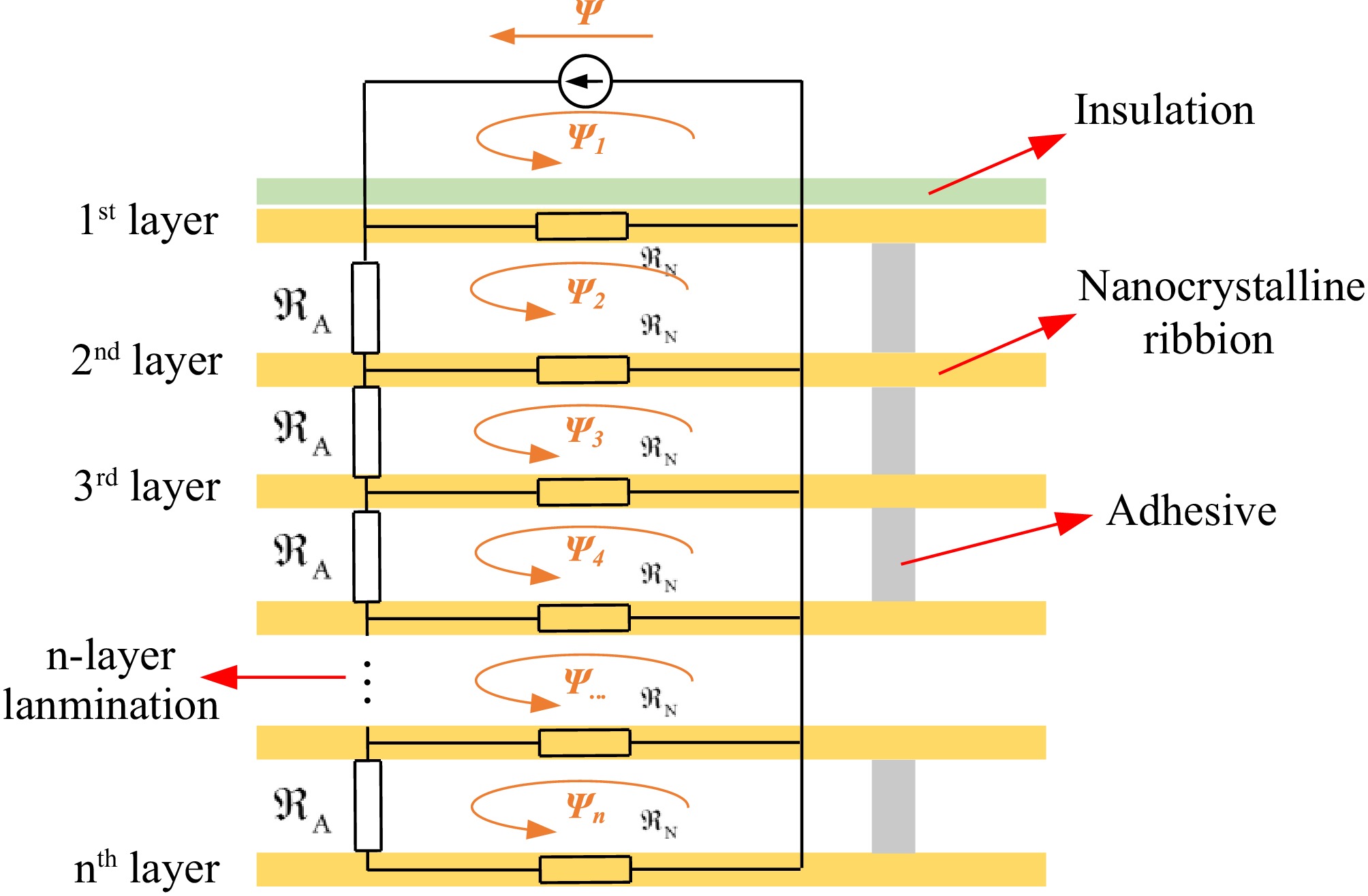
Figure 8.
The magnetic flux and magnetic reluctance distributions entering the n-layer laminated magnetic core structure.
-
Figures 9 and 10 show the general view of the magnetic shielding structure with multi-layer Fe-based nanocrystalline ribbons and the circular coil. The plane of the circular coil is parallel to the nanocrystalline core. The spatial Cartesian coordinate system (x, y, z) and polar coordinate system (ρ, φ, z) are established in the Fig. 9. To characterize the attenuation of electromagnetic fields and waves in laminated nanocrystalline cores, the following assumptions are made regarding electromagnetic waves in an unbounded, linear, and conductive medium:
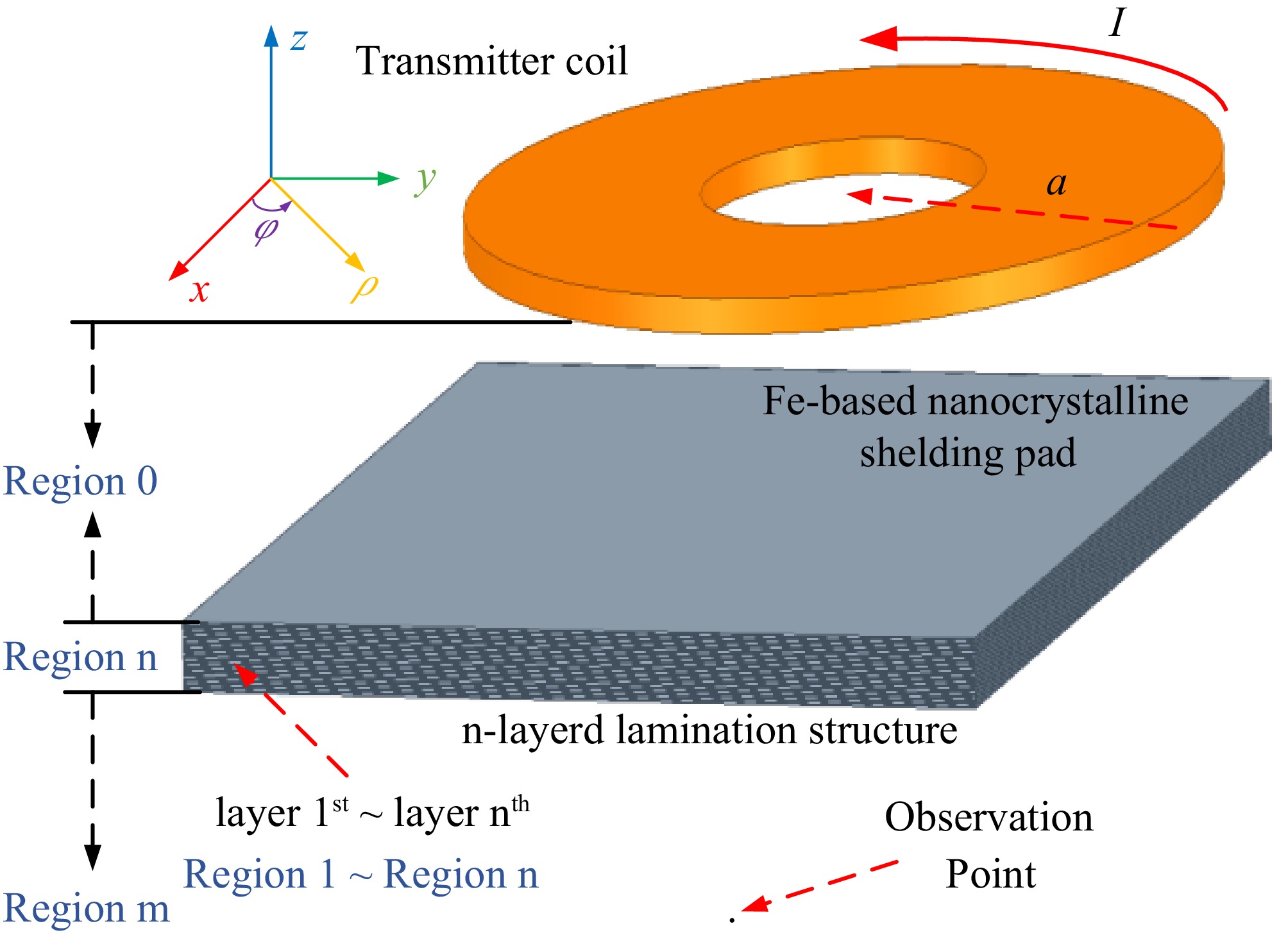
Figure 9.
Model establishment of the magnetic coupler with multi-layer laminated nanocrystalline ribbon core structure.
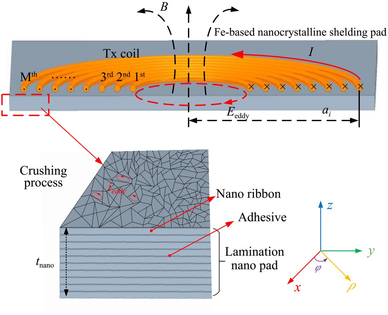
Figure 10.
Magnetic flux and electric field intensity analytical model.
(1) The components of the electric field intensity E and magnetic field intensity H exhibit no directional dependence. In other words, for all regions within the transmission medium
$ \dfrac{\partial }{{\partial x}} = \dfrac{\partial }{{\partial y}} = 0 $ (2) The transmission medium satisfies the charge continuity equation
$ \nabla \cdot {\text{J}} = - \dfrac{{\partial \rho }}{{\partial t}}({A} /{{m} ^3}) $ The space can be divided into three parts according to different planes. Region 0 is the air gap distance between the coil and the shielding layer, Region n is the shielding magnetic core composed of Fe-based nanocrystalline ribbons of n layers, named layer 1st ~ nth, respectively[30]. Region m is the outer area of the shielding layer. The permeability, conductivity, and dielectric constant of the Fe-based nanocrystalline material in Region n are µ, σ, and ε.
Since the magnetic vector potential only contains the φ direction component, the magnetic vector potential in the non-eddy current region can be expressed as:
$ {\nabla ^2}{{\text{A}}_\varphi } = 0 $ (7) The magnetic vector potential in the eddy current region can be expressed as:
$ {\nabla ^2}{{\text{A}}_\varphi } - \gamma _{\text{i}}^2{{\text{A}}_\varphi } = 0 $ (8) where,
$ {\gamma _i} = \sqrt {{\text{j}}\omega \sigma {\mu _i}{\mu _0}} $ $ \left\{ {\begin{array}{*{20}{c}} {{\nabla ^2}{{\mathbf{A}}_\varphi } = \left( {\dfrac{{{\partial ^2}}}{{\partial {\rho ^2}}} + \dfrac{1}{\rho }\dfrac{\partial }{{\partial \rho }} + \dfrac{{{\partial ^2}}}{{\partial {{\text{z}}^2}}}} \right){{\mathbf{A}}_\varphi } = {\text{j}}\omega \mu \sigma {{\mathbf{A}}_\varphi }} \\ {\nabla \times {{\mathbf{A}}_\varphi } = - {{\mathbf{e}}_\rho }\dfrac{{\partial {{\mathbf{A}}_\varphi }}}{\partial } + {{\mathbf{e}}_{\textit{z}}}\left( {\dfrac{{\partial {{\mathbf{A}}_\varphi }}}{{\partial \rho }} + \dfrac{1}{\rho }{{\mathbf{A}}_\varphi }} \right)} \end{array}} \right. $ (9) Firstly, assume that the coil in Fig. 9 is a single turn. The magnetic vector potential in the Regions 0, n, and m can be expressed as Eqn (10) by the Fourier-Bessel integral separating variables method[31−33].
$ \left\{ {\begin{array}{*{20}{l}} {{\text{A}}_\varphi ^{(0)}(\rho ,{\textit{z}}) = \dfrac{{{\mu _0}aI}}{2}\int_0^\infty {\dfrac{\lambda }{{{\tau _0}}}} J(\lambda a)J(\lambda \rho )\left( {{{e} ^{ - {\tau _0}{\textit{z}}}} + {C_0}{{e} ^{{\tau _0}{\textit{z}}}}} \right)d\lambda } \\ {{\text{A}}_\varphi ^{(n)}(\rho ,{\textit{z}}) = \dfrac{{{\mu _n}aI}}{2}\int_0^\infty {\dfrac{\lambda }{{{\tau _n}}}} J(\lambda a)J(\lambda \rho )\left( {{D_n}{{e} ^{ - {\tau _n}{\textit{z}}}} + {C_n}{{e} ^{{\tau _n}{\textit{z}}}}} \right)d\lambda } \\ {{\text{A}}_\varphi ^{(m)}(\rho ,{\textit{z}}) = \dfrac{{{\mu _0}aI}}{2}\int_0^\infty {\dfrac{\lambda }{{{\tau _0}}}} J(\lambda a)J(\lambda \rho ){C_m}{{e} ^{{\tau _0}{\textit{z}}}}d\lambda } \end{array}} \right. $ (10) where, µn is the relative permeability of the n-layer shielding material, σ is the electrical conductivity, ε is the vacuum permittivity, µ0 is the vacuum relative permeability, λ is the Hankel transform integral variable, and a is the outer radius of the single turn coil. There are only forward waves in the free space electromagnetic field, and reverse waves will appear when the high conductivity shielding layer exists.
$ {D_i}{{\text{e}}^{ - {\tau _i}{\textit{z}}}} $ $ {C_i}{{\text{e}}^{{\tau _i}{\textit{z}}}} $ Shielding effectiveness calculation of the Fe-based nanocrystalline ribbon core
-
According to Maxwell's equation as shown in Eqn (11), the electromagnetic field expression of Region 0 can be obtained.
$ \left\{ {\begin{array}{*{20}{l}} {{\mathbf{B}} = \mu {\text{H}} = \nabla \times {\mathbf{A}}} \\ {{\mathbf{E}} = - {j} \omega {\mathbf{A}}} \end{array}} \right. $ (11) $ \begin{aligned} {{\mathbf{B}}_0} & = \dfrac{{{\mu _0}aI}}{2}{{\mathbf{e}}_\rho }\int_0^\infty \lambda J(\lambda a)J(\lambda \rho )\left( {{{\text{e}}^{ - {\tau _0}|{\textit{z}}|}} - {C_0}{{\text{e}}^{{\tau _0}{\textit{z}}}}} \right)d\lambda \\ & \;\;+ \dfrac{{{\mu _0}aI}}{2}{{\mathbf{e}}_{\textit{z}}}\int_0^\infty {\dfrac{{{\lambda ^2}}}{{{\tau _0}}}} J(\lambda a)J(\lambda \rho )\left( {{{\text{e}}^{ - {\tau _0}|{\textit{z}}|}} + {C_0}{{\text{e}}^{{\tau _0}{\textit{z}}}}} \right)d\lambda \\ \end{aligned} $ (12) $ {{\mathbf{E}}_0} = - \dfrac{{{\text{j}}\omega {\mu _0}aI}}{2}{{\mathbf{e}}_\varphi }\int_0^\infty {\dfrac{\lambda }{{{\tau _0}}}} J(\lambda a)J(\lambda \rho )\left( {{{\text{e}}^{ - {\tau _0}{\textit{z}}}} + } \right.\left. {{C_0}{{\text{e}}^{{\tau _0}{\textit{z}}}}} \right)d\lambda $ (13) Among them,
$ {\tau _0} = \sqrt {{\lambda ^2} - k_0^2} ,k_0^2 = {\omega ^2}{\mu _0}{\varepsilon _0} $ $ \begin{aligned} {{\mathbf{B}}_{{\text{noshielding }}}} & = \dfrac{{{\mu _0}aI}}{2}{{\mathbf{e}}_\rho }\int_0^\infty \lambda J(\lambda a)J(\lambda \rho ){{\text{e}}^{ - {\tau _0}{\textit{z}}}}d\lambda \\ &\;\; + \dfrac{{{\mu _0}aI}}{2}{{\mathbf{e}}_{\textit{z}}}\int_0^\infty {\dfrac{{{\lambda ^2}}}{{{\tau _0}}}} J(\lambda a)J(\lambda \rho ){{\text{e}}^{ - {\tau _0}{\textit{z}}}}d\lambda \\ \end{aligned} $ (14) $ {{\mathbf{E}}_{{\text{noshielding }}}} = - \dfrac{{{\text{j}}\omega {\mu _0}aI}}{2}{{\mathbf{e}}_\varphi }\int_0^\infty {\dfrac{\lambda }{{{\tau _0}}}} J(\lambda a)J(\lambda \rho ){{\text{e}}^{ - {\tau _0}{\textit{z}}}}d\lambda $ (15) For each boundary of the laminated nanocrystalline magnetic core, it is required that the tangential components of the electric and magnetic field strengths are equal, that is, the φ component of the electric field on both sides of the boundary is equal, and the ρ component of the magnetic field is equal. Then, for Region n there are both forward waves and reverse waves, which can be analogized as follows:
$ \begin{aligned} {{\mathbf{B}}_{\text{n}}}& = \dfrac{{{\mu _{\text{n}}}aI}}{2}{{\mathbf{e}}_\rho }\int_0^\infty \lambda J(\lambda a)J(\lambda \rho )\left( {{D_{\text{n}}}{{\text{e}}^{ - {\tau _{\text{n}}}{\textit{z}}}} - {C_1}{{\text{e}}^{{\tau _{\text{n}}}{\textit{z}}}}} \right)d\lambda \\ & \;\;+ \dfrac{{{\mu _{\text{n}}}aI}}{2}{{\mathbf{e}}_{\textit{z}}}\int_0^\infty {\dfrac{{{\lambda ^2}}}{{{\tau _1}}}} J(\lambda a)J(\lambda \rho )\left( {{D_{\text{n}}}{{\text{e}}^{ - {\tau _{\text{n}}}{\textit{z}}}} + {C_{\text{n}}}{{\text{e}}^{{\tau _{\text{n}}}{\textit{z}}}}} \right)d\lambda \\ \end{aligned} $ (16) $ {{\mathbf{E}}_{\text{n}}} = - \dfrac{{{\text{j}}\omega {\mu _{\text{n}}}aI}}{2}{{\mathbf{e}}_\varphi }\int_0^\infty {\dfrac{\lambda }{{{\tau _1}}}} J(\lambda a)J(\lambda \rho )\left( {{D_{\text{n}}}{{\text{e}}^{ - {\tau _{\text{n}}}{\textit{z}}}} + {C_{\text{n}}}{{\text{e}}^{{\tau _{\text{n}}}{\textit{z}}}}} \right)d\lambda $ (17) In Eqns (16) and (17),
$ {\tau _{\text{n}}} = \sqrt {{\lambda ^2} - k_{\text{n}}^2} $ $ k_{\text{n}}^2 = {\omega ^2}{\mu _{\text{n}}}\left( {\varepsilon _{\text{n}}} - {\text{j}}\dfrac{{\sigma _{\text{n}}}}{\omega } \right)$ $ \begin{aligned} {{\mathbf{B}}_{\text{m}}} & = \dfrac{{{\mu _0}aI}}{2}{{\mathbf{e}}_\rho }\int_0^\infty \lambda J(\lambda a)J(\lambda \rho ){D_{\text{m}}}{{\text{e}}^{ - {\tau _0}{\textit{z}}}}d\lambda \\ & \;\; + \dfrac{{{\mu _0}aI}}{2}{{\mathbf{e}}_{\textit{z}}}\int_0^\infty {\dfrac{{{\lambda ^2}}}{{{\tau _0}}}} J(\lambda a)J(\lambda \rho ){D_{\text{m}}}{{\text{e}}^{ - {\tau _0}{\textit{z}}}}d\lambda \\ \end{aligned} $ (18) $ {{\mathbf{E}}_{\text{m}}} = - \dfrac{{{\text{j}}\omega {\mu _0}aI}}{2}{{\mathbf{e}}_\varphi }\int_0^\infty {\dfrac{\lambda }{{{\tau _0}}}} J(\lambda a)J(\lambda \rho ){D_{\text{m}}}{{\text{e}}^{ - {\tau _0}{\textit{z}}}}d\lambda $ (19) For the upper and lower boundaries of the n-layer nanocrystalline shielding magnetic core, the tangential components of the electric and magnetic field strength are required to be equal. Thus, the φ component of the electric field on both sides of the boundary is equal, and the ρ component of the magnetic field is equal. Therefore, at the boundary of Regions n and m,
$ {\text{E}}_n^{(\varphi )} = {\text{E}}_m^{(\varphi )},{\text{H}}_n^{(\varphi )} = {\text{H}}_m^{(\varphi )} $ $ {D_{\text{m}}} = \dfrac{{{\mu _{\text{n}}}}}{{2{\mu _0}}}{{\text{e}}^{\left( {{\tau _0} - {\tau _{\text{n}}}} \right){\textit{z}}}}\left( {\dfrac{{{\tau _0}}}{{{\tau _1}}} + \dfrac{{{\mu _0}}}{{{\mu _{\text{n}}}}}} \right){D_{\text{n}}} + \dfrac{{{\mu _{\text{n}}}}}{{2{\mu _0}}}{{\text{e}}^{\left( {{\tau _n} + {\tau _0}} \right){\textit{z}}}}\left( {\dfrac{{{\tau _0}}}{{{\tau _{\text{n}}}}} - \dfrac{{{\mu _0}}}{{{\mu _{\text{n}}}}}} \right){C_{\text{n}}} $ (20) Similarly, for the boundaries of Region 0 and Region 1, there is
$ {\text{E}}_0^{(\varphi )} = {\text{E}}_1^{(\varphi )} $ $ {\text{H}}_0^{(\varphi )} = {\text{H}}_1^{(\varphi )} $ $ {D_1} = \dfrac{{{\mu _0}}}{{2{\mu _{\text{n}}}}}{{e} ^{\left( {{\tau _1} - {\tau _0}} \right){\textit{z}}}}\left( {\dfrac{{{\tau _1}}}{{{\tau _0}}} + \dfrac{{{\mu _{\text{n}}}}}{{{\mu _0}}}} \right) + \dfrac{{{\mu _0}}}{{2{\mu _1}}}{{e} ^{\left( {{\tau _1} + {\tau _0}} \right){\textit{z}}}}\left( {\dfrac{{{\tau _1}}}{{{\tau _0}}} - \dfrac{{{\mu _{\text{n}}}}}{{{\mu _0}}}} \right){C_0} $ (21) $ {C_1} = \dfrac{{{\mu _0}}}{{2{\mu _{\text{n}}}}}{{\text{e}}^{ - \left( {{\tau _1} + {\tau _0}} \right){\textit{z}}}}\left( {\dfrac{{{\tau _1}}}{{{\tau _0}}} - \dfrac{{{\mu _{\text{n}}}}}{{{\mu _0}}}} \right) + \dfrac{{{\mu _0}}}{{2{\mu _1}}}{{\text{e}}^{ - \left( {{\tau _1} - {\tau _0}} \right){\textit{z}}}}\left( {\dfrac{{{\tau _1}}}{{{\tau _0}}} + \dfrac{{{\mu _{\text{n}}}}}{{{\mu _0}}}} \right){C_0} $ (22) The above derivations are based on the premise that the single-turn energized circular coil works independently. In actual working conditions, the coils of the WPT magnetic coupler are usually M-turn densely wound coils structure. Where ai represents the radius of the i-th coil turn in Fig. 10. To simplify the analysis, it is assumed here that the core on one side has no crossover effect on the coil on the other side. Take the transmitter coil side as an example, there is:
$ {{{\mathbf{B}}}_{tx}} = \sum\limits_{i = 1}^M {{{\mathbf{B}}}_{tx,i}} $ (23) $ {{\text{B}}_{{\textit{z}},{\text{ withshielding }}}} = \dfrac{{{\mu _0}{a_i}I}}{2}\sum\limits_{i = 1}^M {\int_0^\infty {\dfrac{{{\lambda ^2}}}{{{\tau _0}}}} J(\lambda {a_i})J(\lambda \rho ){D_m}{{e} ^{ - {\tau _0}{\textit{z}}}}d\lambda } $ (24) $ {{\text{B}}_{{\textit{z}},{\text{ noshielding }}}} = \dfrac{{{\mu _0}{a_i}I}}{2}\sum\limits_{i = 1}^M {\int_0^\infty {\dfrac{{{\lambda ^2}}}{{{\tau _0}}}} J(\lambda {a_i})J(\lambda \rho ){{e} ^{ - {\tau _0}|{\textit{z}}|}}d\lambda } $ (25) Then, by selecting the z component of B at the observation point P, the expression of its shielding effectiveness SE can be calculated as Eqn (26).
$ \begin{aligned} {S_{\text{E}}} & = 20\lg \left| {\dfrac{{{{\text{B}}_{{\textit{z}},{{\bf noshielding }}}}}}{{{{\text{B}}_{{\textit{z}},{{\bf withshielding }}}}}}} \right| \\ & = 20\lg \sum\limits_{i = 1}^M {\left| {\dfrac{{\int_0^\infty {\frac{{{\lambda ^2}}}{{{\tau _0}}}} J(\lambda {a_i})J(\lambda \rho ){{e} ^{ - {\tau _0}|{\textit{z}}|}}d\lambda }}{{\int_0^\infty {\frac{{{\lambda ^2}}}{{{\tau _0}}}} J(\lambda {a_i})J(\lambda \rho ){D_m}{{e} ^{ - {\tau _0}{\textit{z}}}}d\lambda }}} \right|} \\ \end{aligned} $ (26) Magnetic core loss calculation of Fe-based nanocrystalline ribbon core
-
In the WPT system with traditional Mn-Zn ferrite material as the magnetic core, the core loss mainly refers to the hysteresis loss generated in the core. Due to the low resistivity and high electrical conductivity characteristics of the Fe-based nanocrystalline material, the additional eddy current losses should also be considered in WPT systems containing an Fe-based nanocrystalline core.
Hysteresis loss
-
The hysteresis loss can be estimated from FEA simulations using the Steinmetz method and the Steinmetz equation is shown in Eqn (27), where α and β are Steinmetz coefficients.
$ {P_{{\text{core }}}} = {C_{\text{m}}}{f^\alpha }{B_{\max }}^\beta $ (27) Using the material B-H curve and other information provided by the Fe-based nanocrystalline material supplier and pouring it into the magnetic field calculator of ANSYS MAXWELL, the hysteresis loss of the magnetic core can be quickly simulated and analyzed.
Additional eddy current loss
-
Considering the influence of the number of turns of the primary and secondary coils, ai and aj are the radius of the ith turn primary coil or the jth turn secondary coil, there are:
$ {{\mathbf{E}}_{1tx}} = \sum\limits_{i = 1}^M {{{\mathbf{E}}_{1tx,i}}} $ (28) $ {{\mathbf{E}}_{1rx}} = \sum\limits_{j = 1}^N {{{\mathbf{E}}_{1rx,j}}} $ (29) Ignoring the cross-eddy current effects of the primary coil on the secondary magnetic core and the secondary coil on the primary magnetic core, the additional eddy current loss of the Fe-based nanocrystalline core can be expressed as Eqn (30). When the system electrical parameters are determined, a, σ, and μ will directly affect the Peddy.
$ \begin{aligned} &{P_{{\text{eddy }}}} = \int_V \sigma {\left| {{{\mathbf{E}}_{1tx}} + {{\mathbf{E}}_{1rx}}} \right|^2}dV \\ & = \dfrac{{\sigma \mu \omega {I_1}}}{2} \int_0^{2\pi } {\int_0^r {\int_0^{\text{t}} {{{\left| {\sum\limits_{i = 1}^M {\int_0^\infty {\dfrac{\lambda }{u}} } \cdot {a_i}J\left( {\lambda {a_i}} \right)J(\lambda \rho )\left( {{D_1}{{\text{e}}^{ - {\tau _1}{\textit{z}}}} + {C_1}{{\text{e}}^{{\tau _1}{\textit{z}}}}} \right)d\lambda } \right|}^2}} } } d\varphi d\rho d{\textit{z}} \\ & + \dfrac{{\sigma \mu \omega {I_2}}}{2} \int_0^{2\pi } {\int_0^r {\int_0^{\text{t}} {{{\left| {\sum\limits_{j = 1}^N {\int_0^\infty {\dfrac{\lambda }{u}} } \cdot {a_j}J\left( {\lambda {a_j}} \right)J(\lambda \rho )\left( {{D_1}{{\text{e}}^{ - {\tau _1}{\textit{z}}}} + {C_1}{{\text{e}}^{{\tau _1}{\textit{z}}}}} \right)d\lambda } \right|}^2}} } } d\varphi d\rho d{\textit{z}} \\ \end{aligned} $ (30) -
When there is a high-frequency alternating current or an alternating electromagnetic field in a conductor, the current is not uniformly distributed inside the conductor, resulting in a slight current density or uneven magnetic flux density inside the conductor, which triggers the skin effect. For WPT systems operating at medium and high frequencies, on the one hand, the parasitic resistance of the coil will increase, and the power loss will increase, and on the other hand, this may lead to uneven distribution of the magnetic flux density in the magnetic core and lead to the phenomenon of regional magnetic saturation.
To solve the skin effect, the magnetic coupler for WPT systems can be fabricated by using multi-stranded stranded Leeds wires for coil fabrication. However, for laminated nanocrystalline ribbon cores, the relative permeability and conductivity have a direct effect on the skinning depth, and their electromagnetic properties indirectly affect the electromagnetic field distribution in the core of the magnetic coupler. To facilitate the analysis, the normalized skinning depth δg = δ / tr is defined, where δ is the material skinning depth and tr is the material thickness. According to the analysis in section "Flexible nanocrystalline unit and its fragmentation process characteristics”, it can be seen that the magnetic permeability of nanocrystalline ribbon is negatively correlated with the degree of fragmentation, and the relationship between the magnetic permeability and the skinning depth of different nanocrystalline ribbon materials is tested under the condition of 85 kHz operating frequency through Eqn (6), as shown in Fig. 11.
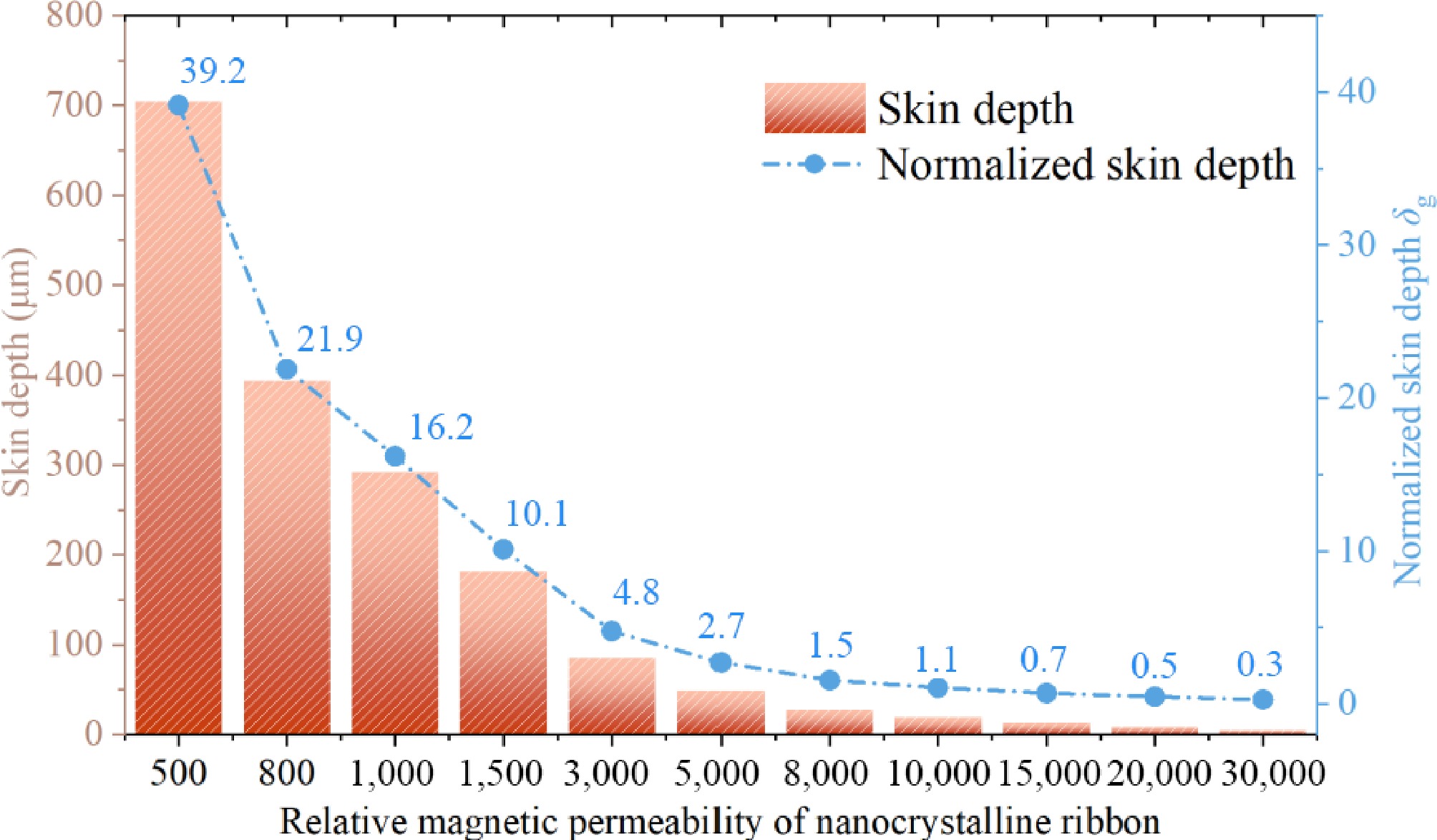
Figure 11.
The relationship between magnetic permeability and skin depth of nanocrystalline materials.
The skin depth is obtained by utilizing the relationship between different magnetic permeability and conductivity of nanocrystalline materials. With the increase of the relative permeability of the nanocrystalline material, the skinning depth gradually decreases, and the ratio of skinning depth to thickness gradually decreases. When the relative permeability is 30,000, the ratio of skin depth to single-layer nanocrystalline thickness is 0.3. The skin depth is smaller than the thickness of single-layer nanocrystal shielding. The magnetic flux is concentrated on the surface of the nanocrystal shielding layer, which leads to the existence of large flux density in some areas of the nanocrystalline ribbon cores under practical working conditions; when the relative permeability is 10,000, the normalized skin depth δg ≈ 1, and the skin depth is almost the same as the thickness. At a relative permeability of 500, the ratio of the skin depth to the thickness of the single-layer nanocrystal is 39.2, and the skin depth far exceeds the thickness of the single-layer ribbon nanocrystal, and the magnetic flux in the nanocrystal shielding layer can be approximated to be uniformly distributed.
Figures 12 and 13 calculate and show the skin depth and normalized skin depth inside the nanocrystalline ribbon core for relative permeabilities from 500 to 30,000 and frequencies from 50 to 200 kHz. As the frequency increases, the skinning depth of the nanocrystalline core gradually decreases, and the normalized skinning depth will gradually decrease, at which time the magnetic flux density will be more and more concentrated at the edge of the nanocrystalline ribbon core layer, which will lead to the problem of regional magnetic saturation and the problem of regional core temperature rise. In summary, this study selects the fragmented nanocrystalline thin-ribbon cores in the range of 500~3,000 relative permeability for the study.
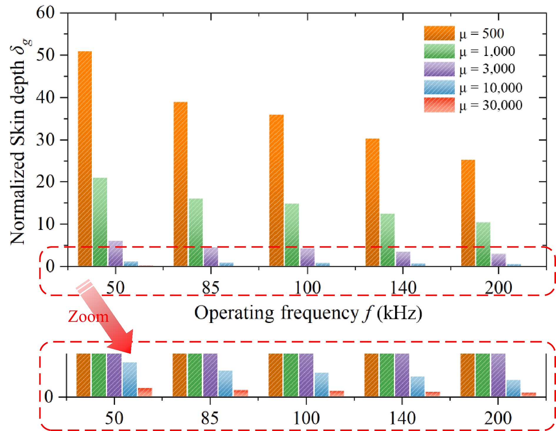
Figure 12.
The trend of normalized skin depth variation under different operating frequencies and relative magnetic permeability.
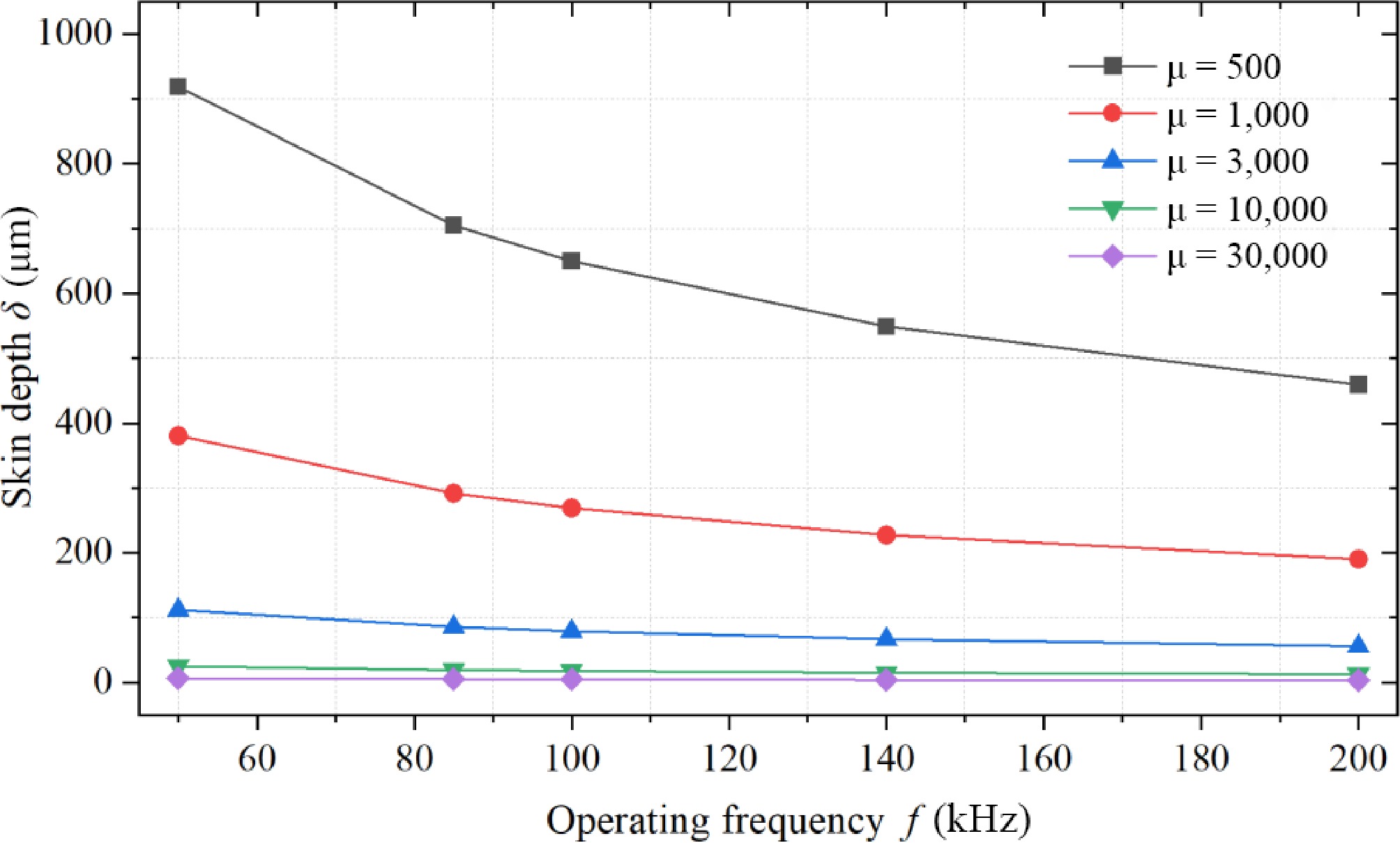
Figure 13.
The trend of skin depth variation under different operating frequencies and relative magnetic permeability.
Hybrid nanocrystalline magnetic structure design for unipolar coils
-
Typical WPT magnetic couplers can be classified into unipolar, bipolar, and multipolar types based on the number of magnetic poles. For instance, the SAE-J2954 international standard for electric vehicle applications specifies unipolar coils, represented by circular coils, and bipolar coils, represented by DD coils, which remain the most widely adopted magnetic coupling structures in WPT systems across various application scenarios. Among these, unipolar coils, as the most commonly used winding structure in WPT systems, demonstrate significant advantages in terms of design complexity, structural versatility, power density, and transmission efficiency.
As described in section "Lamination and transmission characteristics analysis of flexible nanocrystalline", the current common longitudinal and flat laminated nanocrystalline structures still need to account for the magnetic reluctance distribution of unipolar-type coils fully. A typical unipolar circular coil magnetic reluctance model is shown in Fig. 14. Defining
$ {\Re _{\text{s}}} $ $ {\Re _{{\text{m1}}}} $ $ {\Re _{{\text{m}}2}} $ $ \left\{ {\begin{aligned} & {M = \dfrac{{N{\Phi _m}}}{i} = \dfrac{{2{N^2}}}{{{\Re _{m1}} + {\Re _{m2}}}}} \\ & {{L_1} = \dfrac{{N{\Phi _s}}}{i} = \dfrac{{2{N^2}}}{{{\Re _s}}}} \\ & {{L_2} = {L_1} + M} \\ & {k = \dfrac{{{\Phi _m}}}{{{\Phi _s}}} = \dfrac{{{\Re _s}//\left( {{\Re _{m1}} + {\Re _{m2}}} \right)}}{{{\Re _{m1}} + {\Re _{m2}}}} = \dfrac{1}{{1 + \frac{{{\Re _{m1}} + {\Re _{m2}}}}{{{\Re _s}}}}}} \end{aligned}} \right. $ (31) 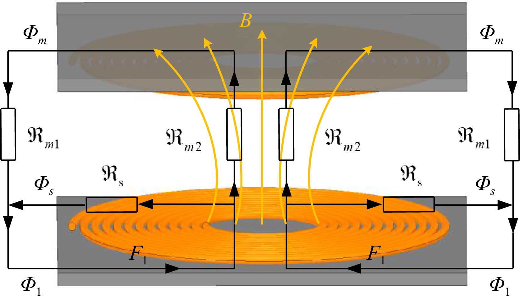
Figure 14.
Equivalent magnetic reluctance model of planar unipolar magnetic coupler.
Specifically, whether flat or vertical laminated structure, the magnetic field distribution trend of the unipolar-type coil has not been fully considered. The magnetic flux lines of unipolar coils exhibit a radially divergent pattern in space. When traditional flat-laminated nanocrystalline cores are employed in unipolar coils, the system achieves a relatively low magnetic reluctance distribution in the XOY plane due to the continuous distribution of the magnetic core. However, along the z-axis, the presence of adhesive between laminated cores results in less effective optimization of magnetic reluctance compared to the XOY plane with a continuous core. Additionally, the flat-laminated nanocrystalline core structure leads to a larger eddy current loop area in the XOY plane, which contributes to significant additional eddy current losses. To further reduce magnetic reluctance, it is feasible to modify the orientation of the nanocrystalline laminations such that the optimal magnetic flux path along the anisotropic direction aligns as closely as possible with the mutual-coupling magnetic reluctance path. When a vertically laminated configuration is adopted, low magnetic reluctance paths are achieved along the x-axis and z-axis, while the y-axis remains a high magnetic reluctance path.
The distribution of magnetic flux density in a typical unipolar coil magnetic coupler is illustrated in Fig. 15. In a unipolar WPT magnetic coupler represented by a circular coil combined with a square magnetic core, the core can be broadly divided into three regions. Area 1 is the central window area of the core not covered by the coil, Area 2 consists of the four sides of the core covered by the coil, and Area 3 includes the four corners not covered by the coil. The width of Area 2 is determined by the coil geometry and the number of turns, and the entire core structure can be approximately divided into a nine-grid pattern. The magnetic cores in these three regions are designed to optimize the magnetic reluctance along different coupling paths, exhibiting significant non-uniformity.
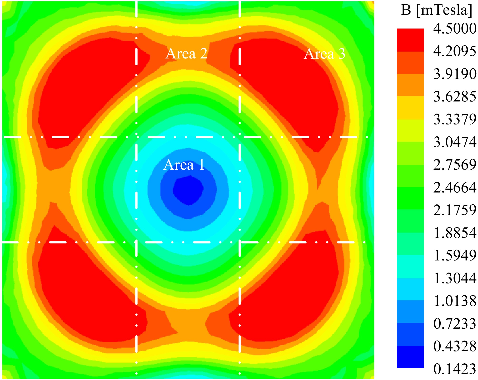
Figure 15.
Distribution of magnetic induction intensity in the magnetic core of a typical unipolar coil magnetic coupler.
Therefore, to circumvent the regional magnetic saturation problem caused by the uneven flux density distribution of traditional WPT cores, with the idea of multi-permittivity toroidal core design[34], this paper proposes a multi-permittivity hybrid nanocrystalline magnetic structure for unipolar coils as shown in Fig. 16. Among them, Area 1 is the main magnetic flux path of mutual coupling, which needs to focus on taking into account the coupling performance and shielding energy efficiency. Area 2 is the secondary magnetic flux region of mutual coupling, which needs to focus on the reduction of the additional eddy current loss problem, and Area 3 needs to focus on the regional magnetic saturation, thermal management, and shielding effect.
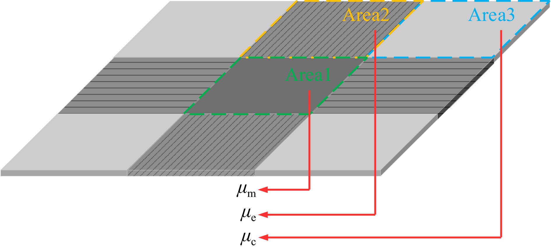
Figure 16.
Multi permeability hybrid nanocrystalline magnetic structure for unipolar coils.
It is well known that high permeability cores in WPT systems bring higher coupling characteristics and potentially higher quality factors. However, for WPTs under Fe-based nanocrystalline cores, when the relative permeability is higher than 600, the enhancement of the coupling characteristics by the permeability increase will become less significant, and the main challenge is the significant additional eddy current loss caused by the high permeability. Therefore, the proposed multi permeability hybrid magnetic structure is designed to minimize both eddy current losses and core losses. In Area 2, a longitudinally laminated arrangement is employed to achieve loss suppression and realize a flux-aligned design for the magnetic field lines. For Areas 1 and 3, the permeability distribution is optimized according to coupling requirements and electromagnetic shielding specifications, adopting a planar laminated magnetic structure that better facilitates electromagnetic shielding. Furthermore, given the polarization characteristics of the magnetic coupler, higher the magnetic flux density in Area 2 compared to Area 1 allows for the strategic placement of a higher-permeability core at the magnetic center. This configuration enhances coupling efficiency while effectively reducing potential leakage flux. Defining µm, µe, and µc as the magnetic permeability of the magnetic cores of Area 1, Area 2, and Area 3, respectively, there are µe < µm < µc.
Furthermore, to minimize core losses in Area 3 where magnetic flux density peaks, the planar laminated structure can be subdivided into three sub-planes designated as Area 3-1, 3-2, and 3-3, as illustrated in Fig. 17. The permeability of the magnetic cores at the three different positions in Area 3 is denoted as µc1, µc2, and µc3, with µc1 < µc2 < µc3. A thin-ribbon nanocrystalline core with lower permeability is positioned closer to the coil, while higher-permeability nanocrystalline materials are layered above in a graded arrangement. This stratified arrangement effectively reduces eddy current losses while maintaining strong overall magnetic coupling. Simultaneously, this design achieves a peak-shaving effect on the maximum loss density distribution, mitigating the uneven loss profile observed in high-permeability cores shown in Fig. 17. Consequently, this design achieves a peak-shaving effect on the maximum loss density, alleviating the uneven loss distribution observed in high-permeability cores shown in Fig. 16. This approach prevents magnetic saturation and thermal imbalance within the core region. The permeability gradient across the three sub-regions ensures optimal magnetic flux guidance, balancing electromagnetic shielding performance with efficient energy transfer throughout the hybrid magnetic system.
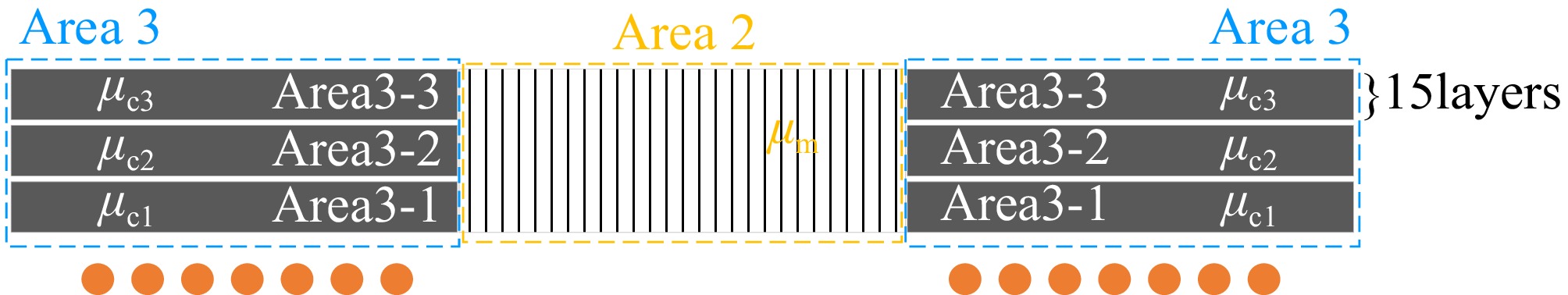
Figure 17.
Three-layer structure of the flat-laminated nanocrystalline in Area 3.
The design principle of the multi-permeability hybrid nanocrystalline magnetic structure is based on reshaping the magnetic flux density distribution within the core using different permeability values. This approach ensures shielding efficiency while optimizing core loss and additional eddy current loss, achieving a balanced distribution of magnetic flux density, as well as electrical, magnetic, and thermal equilibrium within the core. To effectively optimize the permeability design values for each region of the nanocrystalline core, an objective function and constraint equations targeting multi-permeability were established, as shown in Eqns (32) and (33). ANSYS Maxwell finite element simulations were employed to explore different combinations of {µm, µe, µc1, µc2, µc3} within the range of µ
$\in $ $ {\text{Minimize}}\left\{ {\begin{array}{*{20}{c}} {1/k = 1/{f_1}({\mu _m},{\mu _e},{\mu _{c1}},{\mu _{c2}},{\mu _{c3}})} \\ {1/{\text{ALD}} = 1/{f_2}({\mu _m},{\mu _e},{\mu _{c1}},{\mu _{c2}},{\mu _{c3}},{N_p},{N_s},{I_p},{I_s})} \\ {1/{\text{MLD}} = 1/{f_3}({\mu _m},{\mu _e},{\mu _{c1}},{\mu _{c2}},{\mu _{c3}},{N_p},{N_s},{I_p},{I_s})} \end{array}} \right. $ (32) $ {\text{s}}{\text{.t}}{\text{.}}\left\{ {\begin{array}{*{20}{l}} {500 \leqslant ({\mu _m},{\mu _e},{\mu _{c1}},{\mu _{c2}},{\mu _{c3}}) \leqslant 3000} \\ {{\mu _e} \lt {\mu _m} \lt {\mu _c}} \\ {{\mu _{c1}} \lt {\mu _{c2}} \lt {\mu _{c3}}} \\ {{L_{{\text{A2}}}} \propto ({N_p},{N_s},{w_c})} \\ {{W_{{\text{A2}}}} \propto ({N_p},{N_s},{w_c})} \end{array}} \right. $ (33) 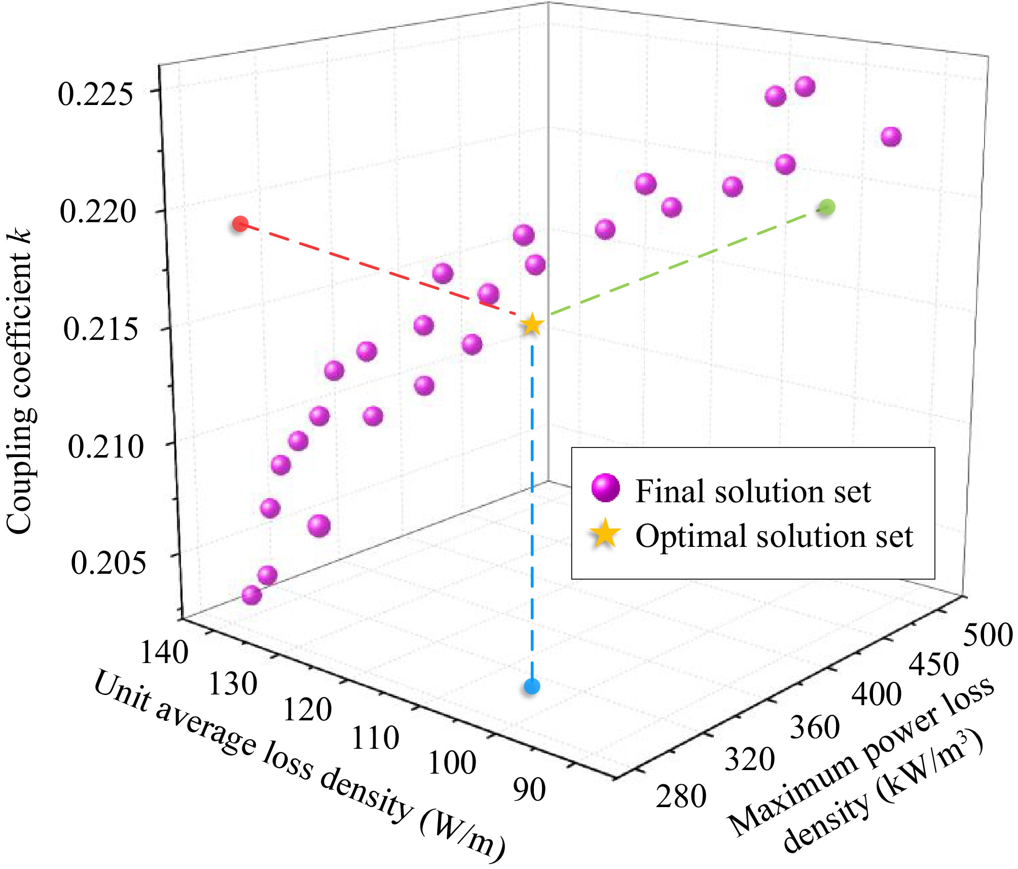
Figure 18.
Optimization design of magnetic permeability for multi permeability hybrid magnetic core structure.
It should be further clarified that Eqns (32) and (33) serve to establish constraint criteria for selecting permeability values in hybrid-permeability magnetic cores, where the specific constraint thresholds must be determined according to actual engineering requirements. For instance, the required coupling coefficient for magnetic cores in electric vehicle applications is less stringent than that for aerospace applications. Moreover, these constraint thresholds could alternatively be defined using other evaluation metrics, such as core temperature, system mutual inductance, or parasitic resistance. Regardless of the chosen constraints, the ultimate objective remains to identify an appropriate set of permeability solutions for optimal design.
-
The proposed hybrid multi-permeability nanocrystalline core pad is shown in Fig. 19a, the nanocrystalline material ribbon used. with a minimum unit thickness of 18 μm was produced by Yuneng Technology Co., Ltd, the material models are u-700, u-1400, and u-3000, and the tested conductivities are 1.0 × 10⁴ S/m, 5 × 10⁴ S/m, and 8.1 × 10⁴ S/m, respectively. The Dynacool-14T comprehensive physical property measurement system and four-probe method are used to measure the conductivity of the proposed nanocrystalline magnetic core, shown in Fig. 20. By applying a DC between the outer two probes, the corresponding voltage drop in the inner two probes can be measured. In this way, the wiring resistance and probe contact resistance can be excluded from the measurement. The resistivity value of the core is averaged from measurements in four different locations along the line.
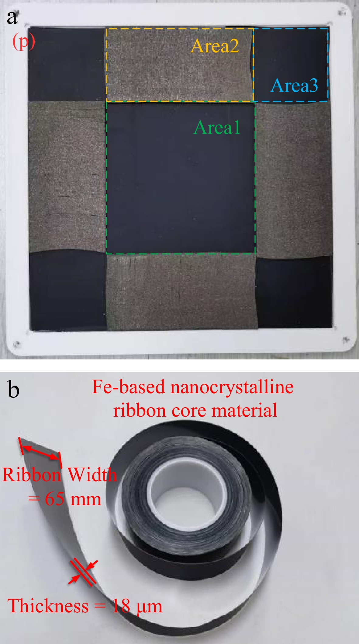
Figure 19.
Hybrid nanocrystalline magnetic core structure and its material units. (a) Proposed hybrid multi permeability nanocrystalline core structure. (b) Fe-based nanocrystalline ribbon core unit.
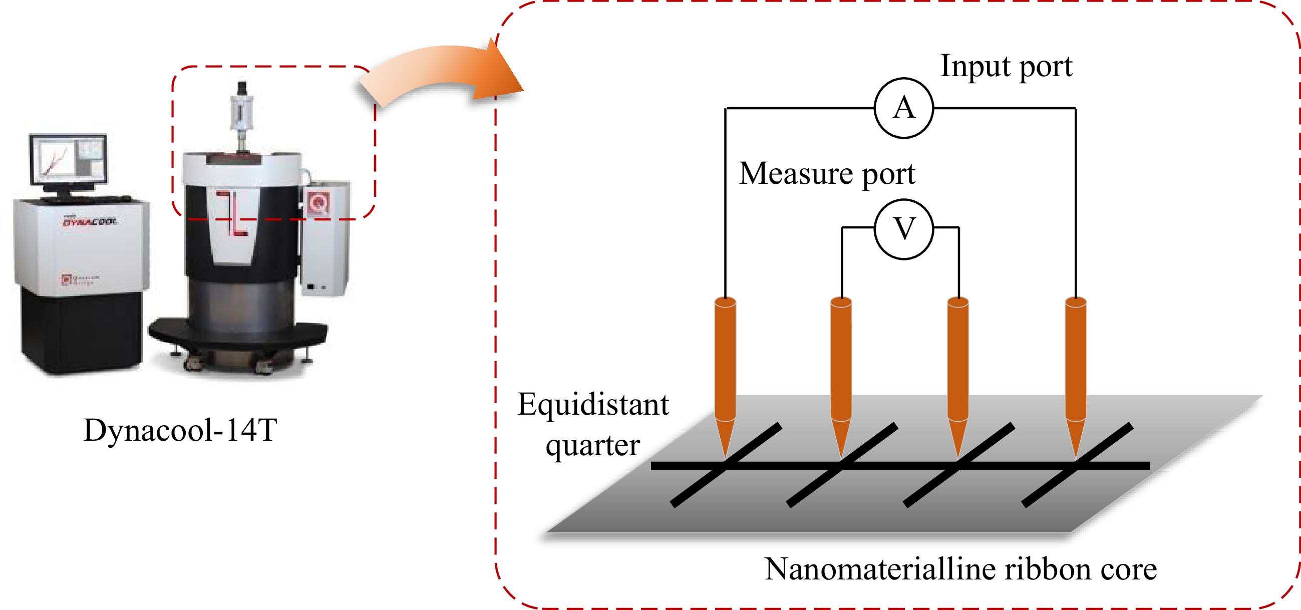
Figure 20.
The Dynacool-14T comprehensive physical property measurement system and four-probe method.
The structures of five different models of laminated Fe-based nanocrystalline and Mn-Zn ferrite cores as experimental control groups are demonstrated in Fig. 21. All magnetic materials are spliced into a 200 mm * 200 mm core pad, and the detailed parameters of the magnetic coupler are shown in Table 2.
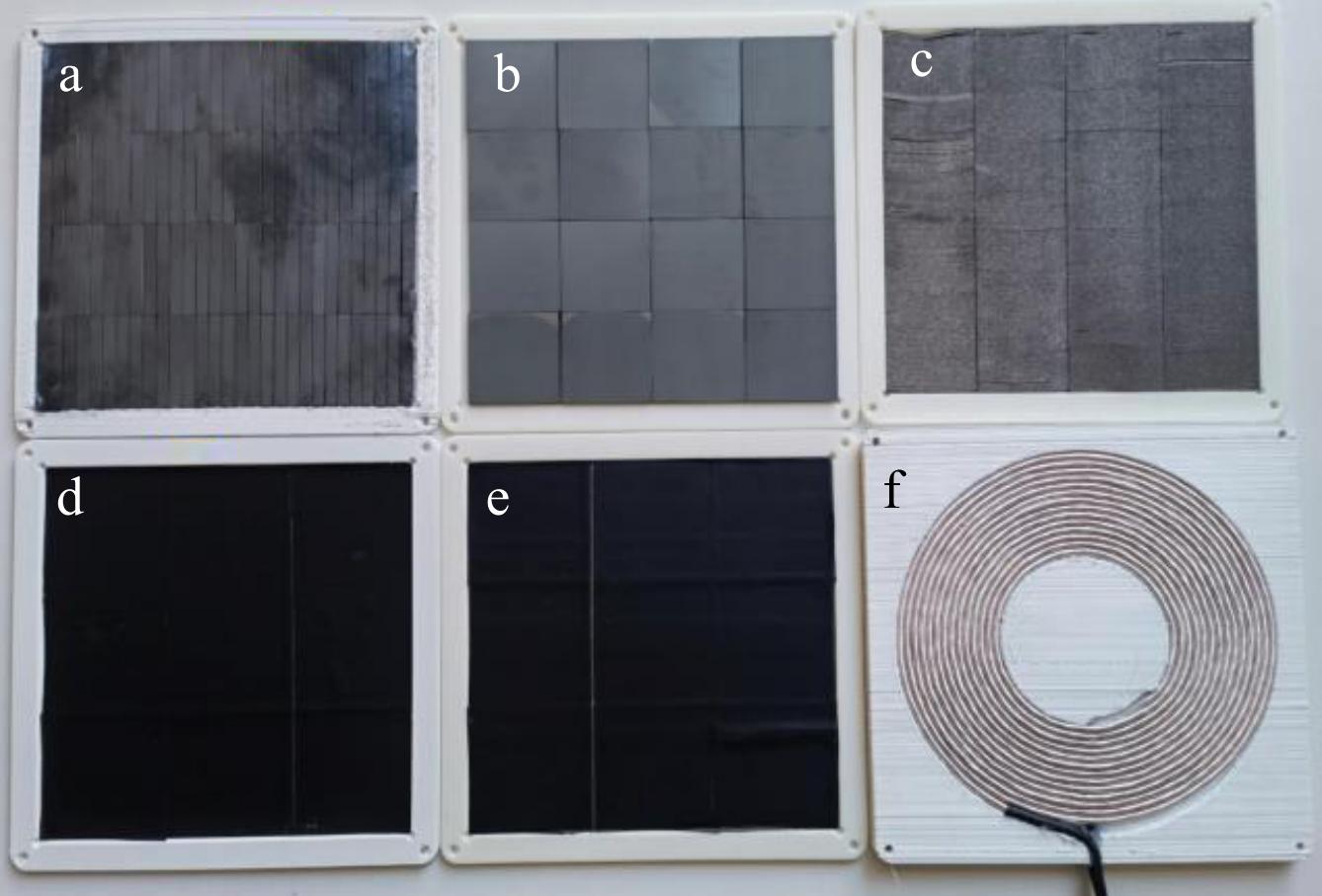
Figure 21.
Schematic of different magnetic cores and coupler.
Table 2. Parameters of the core and coil in the experiment.
Label Material Single size Parameters (a) Vertical cutting nanocrystalline 50 mm width, multiple layers sheets, 2 mm thickness µ = 1,000 (b) PC95 ferrite 50 mm * 50 mm * 5 mm µ = 3,300 (c) Diagonal cutting nanocrystalline 50 mm width, multiple layers sheets, 2 mm thickness µ = 1,000 (d) Flat laminated nanocrystalline 50 mm width, multiple layers, 2 mm thickness µ = 1,000 (e) Flat laminated nanocrystalline 50 mm width, multiple layers,
0.5 mm thicknessµ = 1,000 (p) Hybrid multi permeability nanocrystalline 200 mm * 200 mm * 2 mm µ = 700 µ = 1,400 µ = 3,000 (f) Copper coil with resin shell 0.05 mm * 2,500 strands, spiral tight winding N = 14 The impedance analyzer HIOKI IM3570 was used to measure the transmitter resistance, self, and mutual inductance of the magnetic coupler, where the results are shown in Table 3 compared with the simulated value in ANSYS MAXWELL. The inductance value can be directly obtained through simulation, while the resistance value needs to be obtained by using finite element analysis to determine the magnetic field strength and perform analytical calculations[24]. The resistance contains the DC resistance Rcond, and AC resistance Rindu of the coil[25].
Table 3. Impedance analyzer measurement and finite element simulation results of multiple sets of magnetic core pads,.
Magnetic coupler L1 Simulated value (μH) L1 Measured value (μH) R1 Simulated value (mΩ) R1 Measured value (mΩ) M Simulated value (μH) M Measured value (μH) Only (f) 31.8 33.6 22.5 25.8 9.2 9.6 (a) + (f) 49.8 47.4 47.1 43 21.5 21.9 (b) + (f) 58.4 54.3 33.1 33.9 26.1 26.7 (c) + (f) 51.9 50.5 42.8 39.4 23.8 24.4 (d) + (f) 44.5 51.9 87.5 77.8 21.7 20.1 (e) + (f) 41.4 47.1 102.7 97.9 19.1 18.6 (p) + (f) 53.3 51.7 40.1 38.8 24.0 24.9 To complete the comparative analysis, the ferrite group (b) + (f) was selected as a reference base with four nanocrystalline combination pads. Due to the 50 mA limitation of the impedance analyzer in measuring current, it is difficult to understand the trend of AC resistance variation with coil current through weak current testing. Then, the magnetic field strength H can be solved by using a field calculator in ANSYS MAXWELL and the AC resistance was approximated using the Kelvin equation to analyze and compare the effects of different magnetic core combinations on AC resistances[25].
By adjusting the input DC current, the fluctuation of the AC resistance of the transmitter coil under different input DC current conditions are shown in Fig. 22. To compare the fluctuations in resistance, defining the AC resistance fluctuation rate (RFR) to characterize the variation in internal resistance under different test current conditions. The RFR is calculated as Eqn (34), where Rmin is the minimum resistance value within the test range, and Rav and Rmax are the average and maximum values of the AC resistances, respectively.
$ {\text{RFR}} = \dfrac{{{R_{\max }} - {R_{\min }}}}{{{R_{{\text{av}}}}}} \times 100{\text{%}} $ (34) 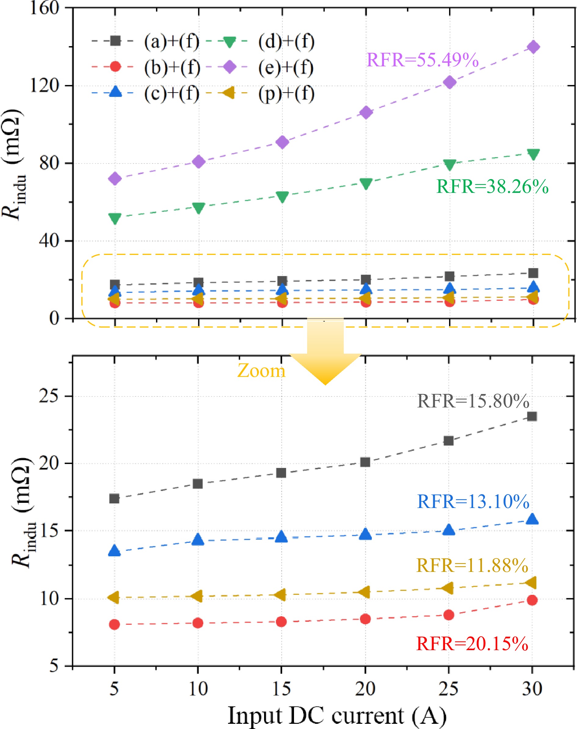
Figure 22.
The fluctuation of the AC resistance of the transmitter coil under different input DC current conditions.
As can be observed, as the test current increases, the magnetic field intensity H in the coil-covered region increases, leading to a rise in Rindu. Among the several types of magnetic cores, vertical laminated nanocrystalline (a) and the proposed diagonal laminated nanocrystalline structure (c) exhibit RFR values of 15.80% and 13.10%, respectively. The proposed multi-permeability hybrid magnetic structure (p) showed a superior RFR of 11.88%., indicating that the parasitic resistance is less affected by fluctuations. Although the coil of Mn-Zn ferrite core has a small AC resistance, its RFR is relatively high due to the average value. This indicates that as the coil current increases, that is, as the power increases, the magnetic density distribution in the magnetic core of the magnetic coupler begins to become very uneven. So, it causes significant fluctuations in parasitic resistance and an imbalance in thermal distribution.
In contrast, the other two flat laminated nanocrystalline structures (d) and (e) show higher RFR fluctuations, their AC resistance values have exceeded DC resistance and occupied the main part of copper loss, becoming very uncontrollable. All resistance calculations are based on the primary side, and due to the symmetry of the magnetic coupler, the characteristics of the receiving coil can be considered similar to of the transmitter. It is important to note that due to the complexity of the magnetic structure errors, the approximation errors in the homogeneous medium method, and the finite element simulation errors caused by neglecting thermal effects, there may still be some discrepancies between the actual Rindu values and the estimated values.
In the nanocrystalline group, the proposed multi permeability hybrid magnetic structure has high self-inductance, low resistance, and low RFR with high coil quality factor, which is favorable for the high-efficiency design of the system in S-S topology. The measured conclusions are consistent with those obtained from the magnetic reluctance analysis in previous section.
Development of the experimental platform and 3-kW power experiments
-
To further verify the superiority of the proposed structure, a 3-kW magnetic coupler prototype, and a WPT system platform are constructed, as shown in Fig. 23, with a transmission distance of 50 mm for the magnetic coupler. The system is based on an S-S topology design, and the electrical schematic and design parameters are shown in Fig. 24 and Table 4. The STMicroelectronics microcontroller STM32F407 is employed to generate 4-channel PWM signals to drive the SiC MOSFETs in the H-bridge inverter, and the switching frequency is 85 kHz.
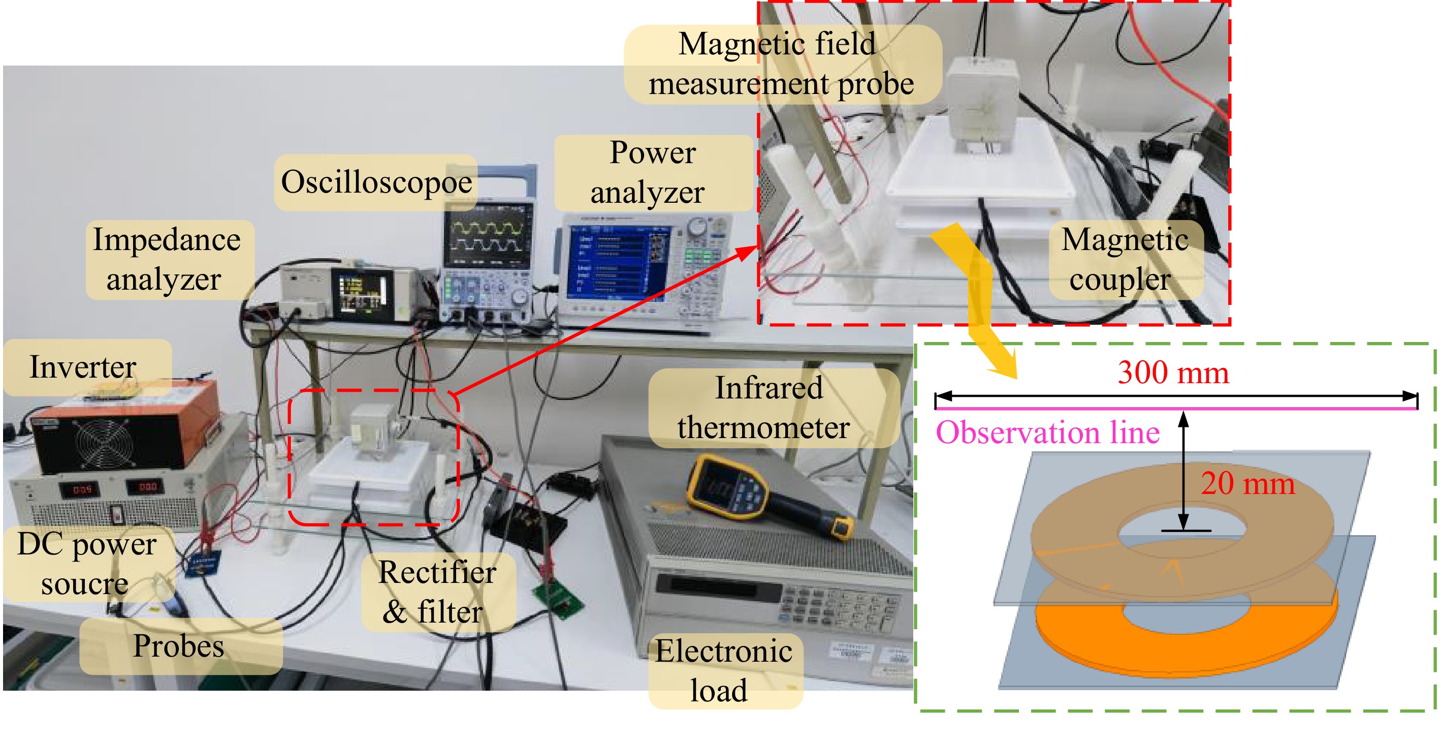
Figure 23.
The proposed 3 kW WPT system prototype and experimental platform with S-S topology.
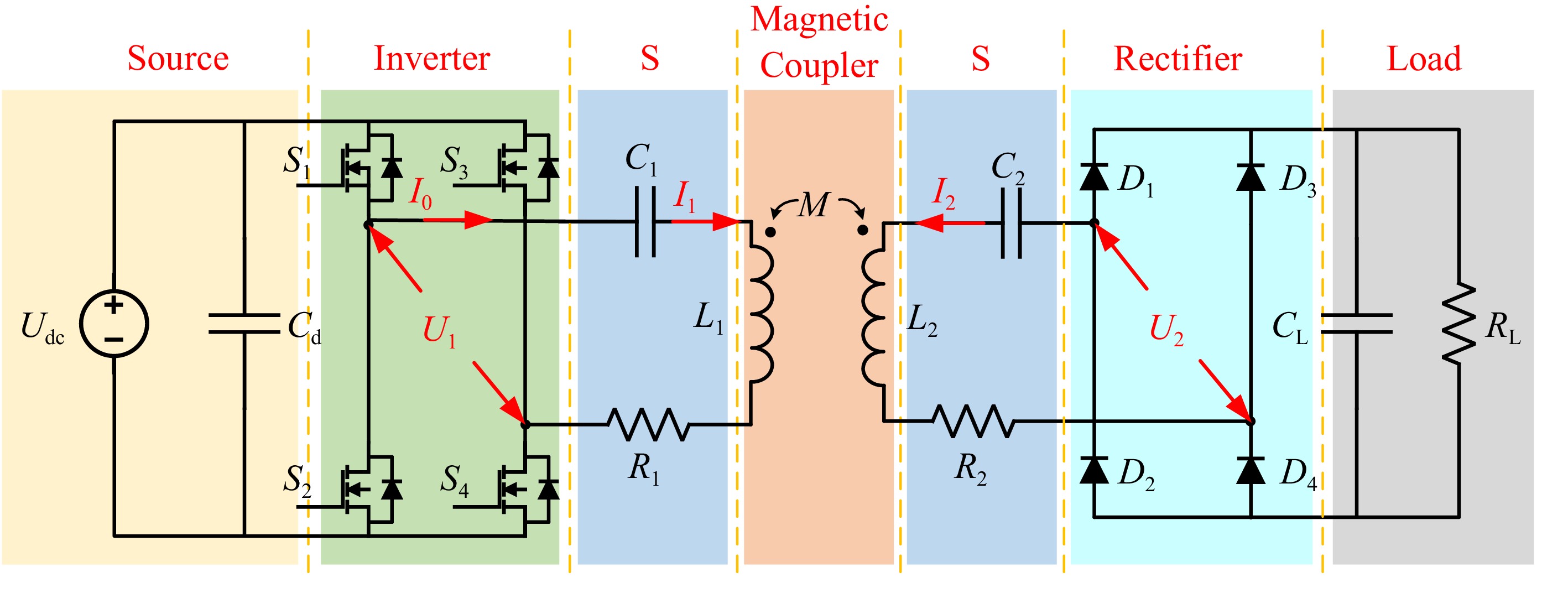
Figure 24.
Circuit schematic diagram of the experimental platform.
Table 4. Electrical parameter values of the experimental platform.
Parameters Description Value Udc Input DC voltage 160 V f Operating frequency 85 kHz L1 Primary self-inductance 53.3 μH C1 Primary compensation capacitance 65.1 nF L2 Secondary self-inductance 53.7 μH C2 Secondary compensation capacitance 65.2 nF RL Load resistance 11 Ω Two pairs of RIGOL RP1025D voltage probes and HIOKI CT6711 current probes are used for waveform acquisition and measurement. Figure 25 shows the voltage-current waveform states of the input and output ports measured using a Yokogawa DLM3034 oscilloscope. The developed MCR-WPT system has good resonance conditions when the magnetic coupler is fully aligned. When the coupler is fully aligned, the phase of U1 slightly leads the I1, achieving zero voltage switching (ZVS). The switching loss of the inverter MOSFETs is greatly reduced. Figure 26 shows the system efficiency under the measurement conditions using the PX8000 power analyzer, and the system with the proposed hybrid structure can achieve an efficiency higher than 93.8% when the hybrid core structure transmits a power of 3 kW in the fully aligned state. The efficiencies are 95.1%, 90.1%, and 92.5% when using cores (b), (e), and (c) in Fig. 21, respectively. The efficiency of the proposed hybrid core structure is slightly lower than that of ferrite cores but higher than that of other types of nanocrystalline cores.
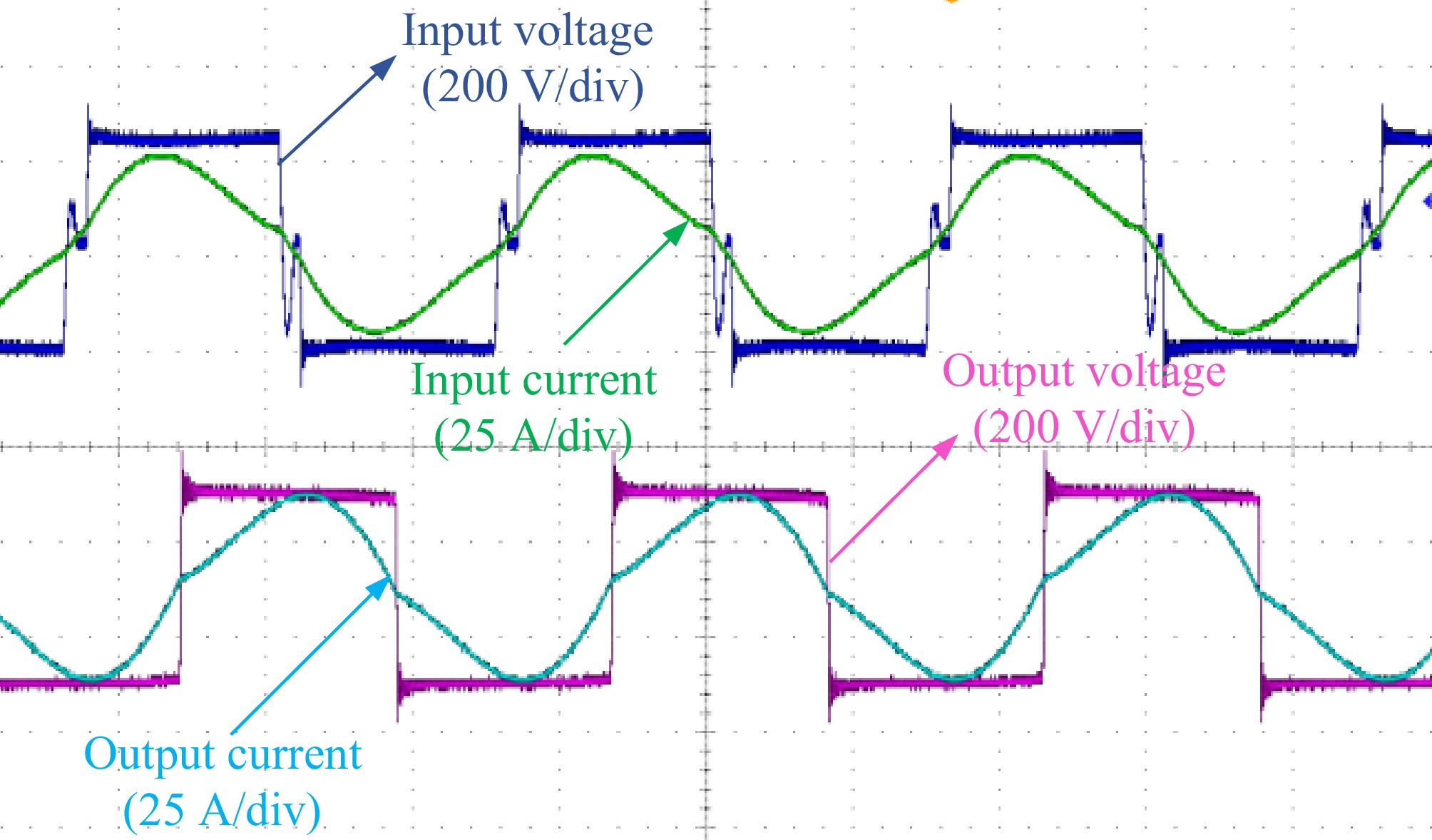
Figure 25.
Voltage and current waveform when transmitting 3 kW power.
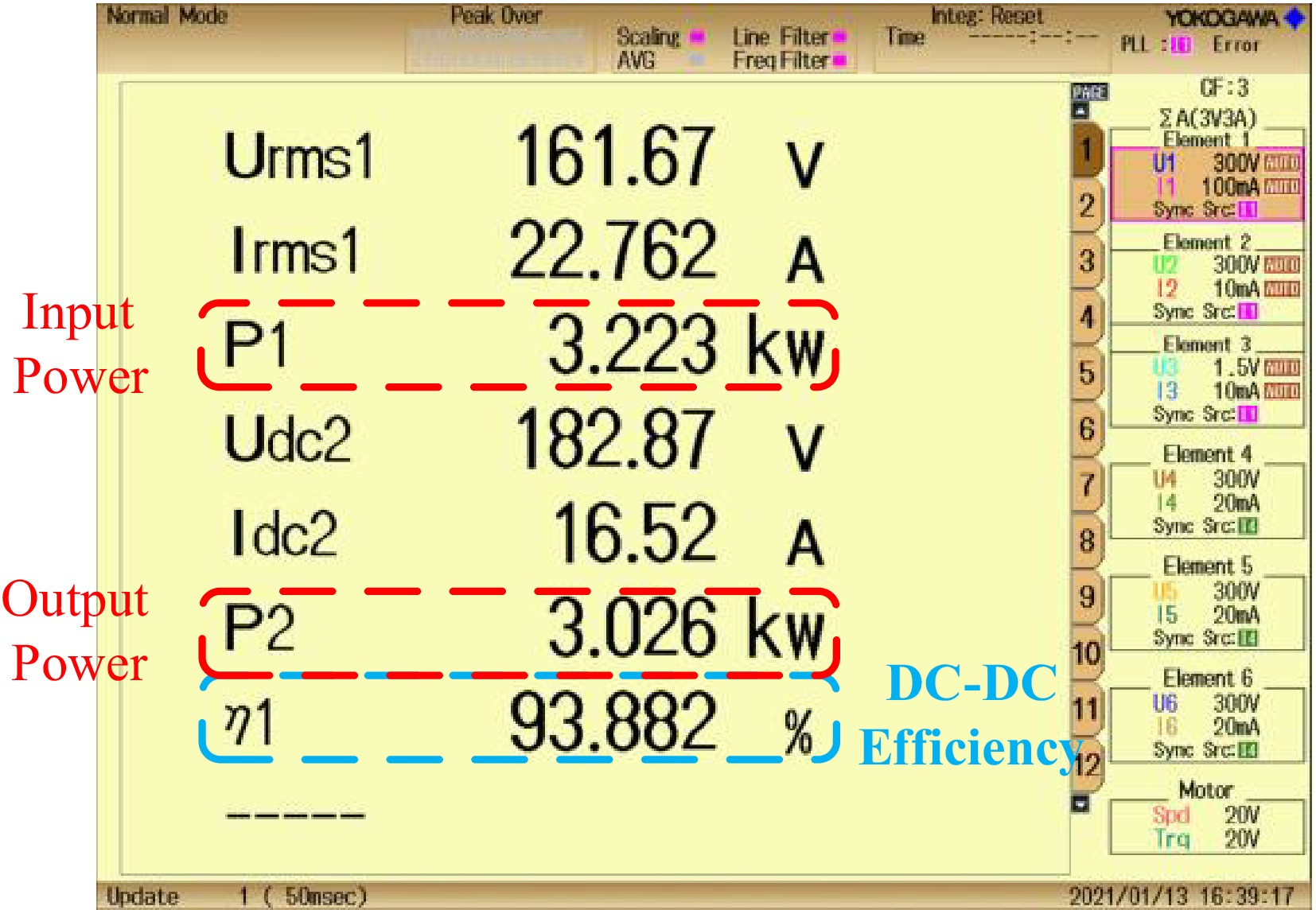
Figure 26.
System efficiency when transmitting 3 kW power at fully aligned state.
Figure 27 shows the simulated and measured values of system efficiency under different test current conditions. It can be seen that, despite the continuous increase in system power, the proportion of total system loss remains stable within a certain range. When the input current exceeds about 20 A, the system achieves maximum efficiency and maintains efficient operation, while the trends shown in the simulations align well with the experimental results.
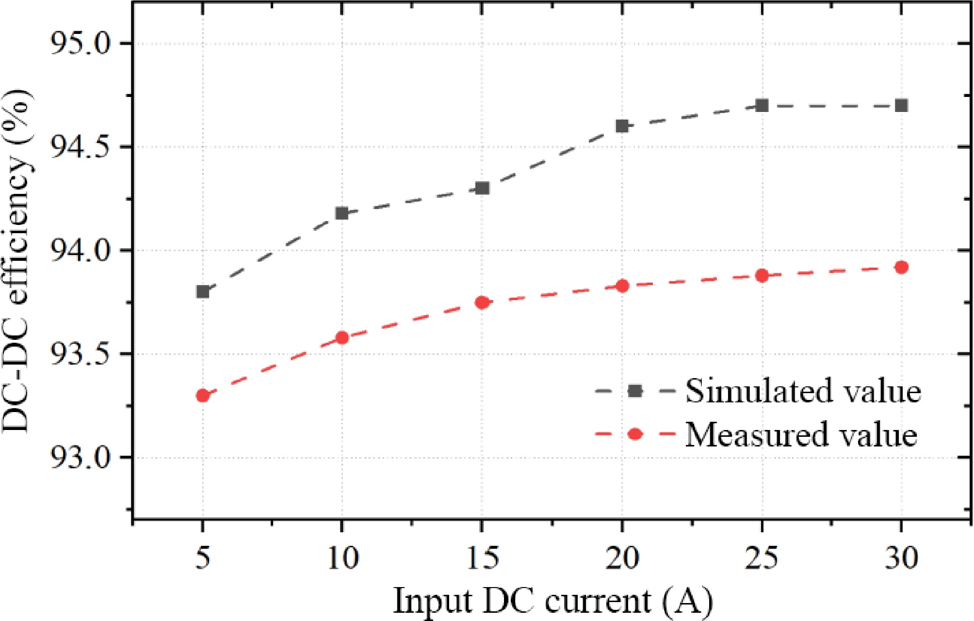
Figure 27.
System DC-DC efficiency under different input DC current conditions.
Shielding energy efficiency and EMC experiments
-
To verify the shielding effectiveness of the proposed magnetic structure, magnetic flux density measurements were performed along the observation line in Fig. 23 using the magnetic field measurement probe Narda EHP-200. The measurement results presented in Fig. 28 show that the shielding energy efficiency of the proposed hybrid core structure is slightly better than that of the Mn-Zn ferrite core, which complies with the constraints on leakage magnetic flux density in the ICNIRP guidelines. In terms of dimensions, the proposed hybrid nanocrystalline core reduces the volume by about 32.5% and the weight by 15.6% compared with the ferrite core in the control group, which realizes the lightweight design of the system and improves the power density to a large extent. The proposed hybrid nanocrystalline cores still have good deformation capability under the condition of high-performance adhesive, which is potentially useful in special anisotropic WPT systems, such as curved or bowl-shaped structures for underwater and aerospace WPT applications.
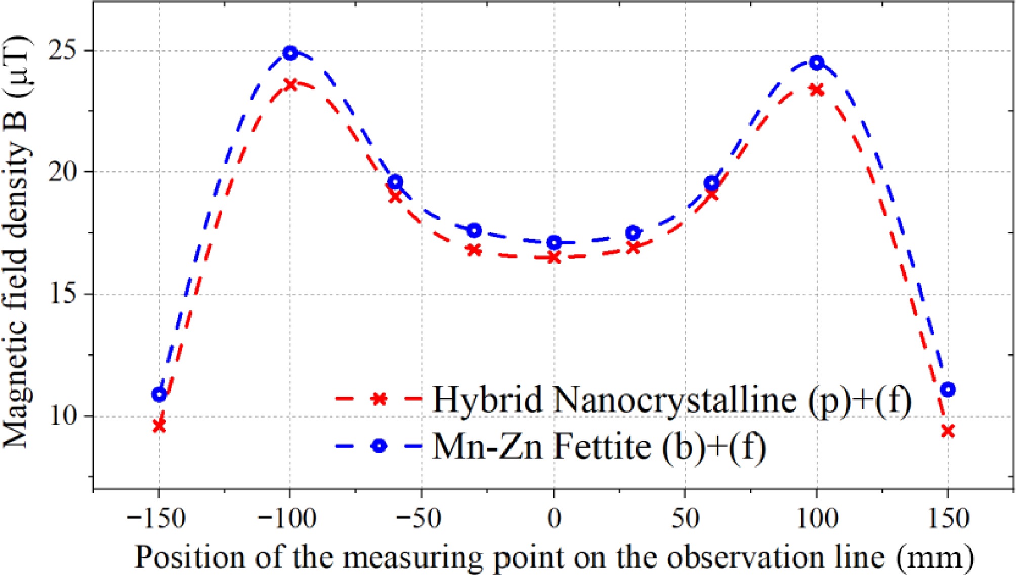
Figure 28.
Magnetic flux density curve measured along the observation line.
Discussion on limitations and future application potential
-
From the perspective of current nanocrystalline manufacturing processes and costs, the proposed multi-permeability hybrid magnetic structure is undoubtedly complex and expensive. For most magnetic material manufacturers, nanocrystalline cores are primarily produced in the form of thin ribbons or magnetic rings to meet existing application demands. Given the current progress in WPT engineering, even flat laminations have not yet seen widespread adoption in the context of electric vehicle WPT technology, with only a few research teams exploring them in prototype studies. Therefore, although the proposed multi-permeability hybrid magnetic structure involves more complex processes and higher manufacturing costs, these expenses are inversely proportional to the scale of production and demand. Once WPT technology becomes widely adopted, it is believed that these processes will not become a bottleneck. Similar to the development of smartphone wireless chargers, as products continue to emerge, their costs have steadily decreased.
From the perspective of integration and reliability, the proposed novel magnetic structure undoubtedly exhibits excellent mechanical flexibility and impact resistance, enabling it to adapt to complex working environments and various enclosure shapes. Combined with the experimental results, the multi-permeability hybrid design effectively achieves lower eddy current losses and reduced parasitic resistance fluctuations. This indicates that as the power of the WPT system increases the loss distribution and thermal distribution of the core becomes more balanced. This is highly beneficial for improving system reliability, adaptability, and thermal equilibrium.
It is worth noting that the proposed multi-permeability hybrid magnetic core has promising prospects for modular design. The core can be divided into different modular units, allowing for modular construction based on power levels, coil dimensions, and shapes. This has universal significance for its future engineering applications. Furthermore, with the future integration of advanced technologies such as 3D printing of composite magnetic materials, it will achieve a balance between performance and cost-effectiveness for mass production.
-
This paper comprehensively analyzes the requirements for the application of iron-based nanocrystalline flexible thin-ribbon materials in wireless energy transmission systems and proposes a general modeling of thin-ribbon laminated nanocrystalline core structures and an analytical calculation method for shielding energy efficiency and losses. On this basis, a novel hybrid multi-permeability Fe-based flexible nanocrystalline ribbon laminated magnetic structure is proposed for a typical unipolar coil magnetic coupler, which significantly reduces the additional eddy current loss of the traditional lay-flat laminated nanocrystalline structure and has an excellent electromagnetic shielding effect. Through multiple comparative experiments and analyses, the proposed magnetic structure achieves a transmission efficiency higher than 93.8% in the 3 kW WPT system, and the shielding effect is almost comparable to that of Mn-Zn ferrite cores and reduces the weight and volume of the cores by 15.6% and 32.5%, respectively, thus realizing the lightweight design of the system.
In addition to its advantages in volume and weight reduction for the compact and lightweight design of WPT systems, the proposed novel magnetic structure undoubtedly exhibits superior mechanical flexibility and impact resistance, enabling it to adapt to complex working environments. Secondly, the multi-permeability hybrid design effectively reduces core eddy current losses and thermal effects, enhancing the overall efficiency and electromagnetic compatibility of the system. Finally, its modular design facilitates customized manufacturing and installation. With the future integration of advanced technologies such as 3D printing of composite magnetic materials, it will achieve a balance between performance and cost-effectiveness for mass production.
In summary, through multi-dimensional performance optimization, the multi-permeability hybrid magnetic structure not only meets the core requirements for power transfer in wireless charging systems but also achieves significant breakthroughs in key engineering metrics such as reliability, adaptability, and energy efficiency. Currently, the annual global production of Fe-based nanocrystalline materials has exceeded 1 million kilograms and is still growing. This unique magnetic structure is capable of adapting to a wide range of application scenarios, including electric vehicles, robotics, drones, submersibles, and spacecraft. It offers a highly competitive solution for next-generation high-efficiency, high-power-density wireless power transfer technologies.
This work was supported in part by the National Key Research and Development Program of China (Grant No. 514010202-302), the Central Science and Technology Commission of China (Grant No. JJKJW20200021), the National Natural Science Foundation of China (Grant No. 52107002), and the Civil Space Technology Advance Research Program of China.
-
The authors confirm contribution to the paper as follows: study conception and design: Wang D, Cui S; data collection: Wang D, Bie Z; analysis and interpretation of results: Wang D, Zhang J; draft manuscript preparation: Wang D, Zhu C. All authors reviewed the results and approved the final version of the manuscript.
-
All data generated or analyzed during this study are included in this published article.
-
The authors declare that they have no conflict of interest.
- Copyright: © 2025 by the author(s). Published by Maximum Academic Press, Fayetteville, GA. This article is an open access article distributed under Creative Commons Attribution License (CC BY 4.0), visit https://creativecommons.org/licenses/by/4.0/.
-
About this article
Cite this article
Wang DA, Cui S, Zhang J, Bie Z, Zhu C. 2025. Modeling and application of hybrid multi permeability Fe-based flexible nanocrystalline laminated ribbon core structure in WPT systems. Wireless Power Transfer 12: e014 doi: 10.48130/wpt-0025-0010 

Modeling and application of hybrid multi permeability Fe-based flexible nanocrystalline laminated ribbon core structure in WPT systems
- Received: 11 December 2024
- Revised: 09 April 2025
- Accepted: 15 April 2025
- Published online: 29 May 2025
Abstract: Flexible soft magnetic materials represented by nanocrystalline have been widely used in magnetic couplers of wireless power transfer systems due to their superior electromagnetic properties and mechanical flexibility in recent years. However, the high conductivity characteristics and thinner material unit thickness of nanocrystalline materials expose additional issues. This article first proposes a general modeling and analytical calculation method for shielding energy efficiency and loss of the nanocrystalline laminated magnetic core structure. Then, a novel hybrid multi-permeability Fe-based flexible nanocrystalline laminated ribbon magnetic structure is proposed. By multi-objective optimization of the permeability, the additional eddy current loss has been significantly reduced. In addition, the transmission performance of the proposed magnetic structure is compared with five similar structures in experiments. Results show that the system transmission efficiency is higher than 93.8% when transmitting 3 kW power and has a superior electromagnetic shielding effect. The proposed structure leads to a significant reduction in weight and volume, which is conducive to the lightweight design and efficient operation of the system. The novel structure achieves a uniform distribution of magnetic flux density while enabling effective thermal management and electromagnetic compatibility of the magnetic coupler, which contributes to the long-term reliable operation of the WPT system.