


-
Wireless power transfer (WPT) has emerged as a prominent technology for charging electric vehicles (EVs)[1,2], and unmanned aerial vehicles (UAVs)[3−5]. However, practical implementation faces a significant challenge: precise positioning of EVs and UAVs within predefined charging areas is often compromised by operational factors, leading to misalignment between charging couplers. This misalignment invariably diminishes charging efficiency, necessitating high tolerance to ensure consistent output characteristics in wireless charging systems[6].
To address this issue, researchers have explored circuit and coupler structure designs[7−12]. For instance, Yang et al. proposed an inductive power transfer (IPT) system based on a clamping circuit with a reconfigurable rectifier, demonstrating high anti-interference capabilities[7]. Budhia introduced a DD coupler that expands the charging zone fivefold compared to square coils[13]. Further innovations include a series-parallel-series topology enabling rated power transmission under pronounced misalignment, an optimization method for DD coil spacing and core length to enhance coupling coefficients, and the addition of reverse compensation coils to DD couplers for improved offset resilience and reliable efficiency from bias to alignment[14,15]. Collectively, these studies reveal a common limitation: anti-offset characteristics are confined to small areas, failing to maintain high tolerance when the receiving coil moves arbitrarily above the transmitting coil.
To overcome this constraint, array coil configurations have been investigated. A three-layer hexagonal PCB winding array ensures stable power delivery regardless of position or orientation[16], while a universal non-contact charging platform with localized characteristics validates flexible and efficient energy transmission[17]. Other solutions include reconfigurable array platforms with two-step search strategies to mitigate insufficient tolerance and low efficiency in multi-UAV charging systems[18], and transmitter-embedded metasurfaces that focus magnetic fields via negative permeability properties, boosting coupling coefficients and efficiency[19]. Despite these advances, critical drawbacks persist. Increased matching circuitry introduces unwarranted losses, and reverse compensation coils may reduce leakage fields, inadvertently lowering efficiency. Overly complex coupler structures also exacerbate coil losses, posing risks in practical applications: UAVs docking in weak energy zones suffer severe efficiency drops, prolonging charging times, and degrading performance, while power fluctuations during movement within the transmission area accelerate battery degradation.
To enhance horizontal misalignment tolerance, this paper proposes an m × n reconfigurable transmitter coupler. By employing coil switching instead of multi-layer compensation, this design mitigates the complexity inherent in array coils. Although slightly more intricate than conventional couplers, it effectively compensates for weak magnetic field regions, improving coupler tolerance. The design's efficacy is verified through simulations and experiments, with results indicating charging efficiencies exceeding 90% over short distances, and stable efficiency zones covering over 80% of the coupler area. Its reconfigurable nature further enables adaptation to diverse scenario-specific geometries.
-
According to Biot-Savart's law, the magnetic field strength in the central area of a square coil is greater than that of a rectangular coil of the same size. As the offset occurs, the trend of mutual inductance between the receiving coil and the transmitting coil in both types of coils is roughly shown in Fig. 1. To enhance energy transfer efficiency, it is necessary to maximize the mutual inductance of the coil as much as possible. Therefore, the square coil is chosen as the basic structure of the transmitting coil. The m × n transmitter coupler designed in this paper is composed of m × n square coils spliced together. To achieve the goal of uniform magnetic field distribution and efficient energy transmission, collaborative design is needed for the current direction, laying method, and connection method of the square coils.
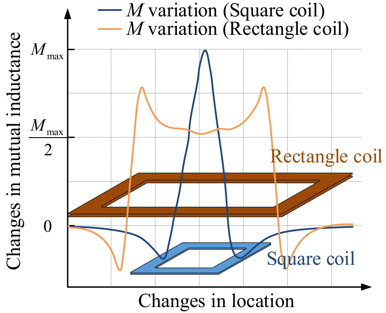
Figure 1.
The variation of mutual inductance within the range of square coils and rectangular coils with coil offset.
According to Faraday's electromagnetic induction, when adjacent coil currents flow in opposite directions, the magnetic fields overlap with each other, and the magnetic field strength in the central area is increased. Therefore, by setting the opposite current flow direction of adjacent coils, the effective energy transfer area can be increased, the energy transfer efficiency can be improved, and the magnetic field distribution in the energy transfer area can become smoother.
However, the magnetic field at the edges of the coil is severely reduced due to the influence of reverse superposition. Meanwhile, due to the opposite direction of the magnetic field, polarity reversal is inevitable when the UAV moves between the two coils. To solve these two problems, it is necessary to intervene in the compensation coil to pull up the magnetic field intensity curve, and to apply a current switching strategy to solve the problem of magnetic field polarity reversal.
To ensure that there is no significant change in magnetic field intensity before and after compensation, the relevant parameters of the compensation coil (such as coil shape, side length, number of turns, etc.) should be consistent with the transmitting coil. The center of the square coils that make up the compensation coil should be set in the lower magnetic field area of the transmitting coil, structurally at the intersection of four adjacent square right angles. In this paper, the compensation coil is uniformly named the judging coil.
Analysis of transmission characteristics
-
The trend of mutual inductance between two coils in a spatial magnetic field is the same as the trend of magnetic field strength change in the area where the coil is located[20]. Therefore, the change in mutual inductance between the coils can also be converted into a change in magnetic field strength in the area where the coil is located. The S-S topology is selected as the compensation topology in this paper to provide a constant current for the power supply of the UAV. According to the existing research[10,21], the frequency, internal resistance, load, and the mutual inductance between the couplers are revealed to influence the output power and transmission efficiency. If the parameters of the system are determined, then the mutual inductance between the couplers would be a critical factor influencing both system power and transmission efficiency.
As a receiving coil, circular coils have a smoother magnetic field distribution from the center to the sides compared to square coils, and have better resistance to rotational offset[22,23]. Considering the rotation that may occur during the flight of the UAV, the circular coil is selected as the receiving coil in this paper to ensure the anti-rotation offset ability of the system. When the UAV moves above the wireless charging platform (WCP), the relationship between mutual inductance and displacement can be solved by the Neumann formula[24]:
$ M = {N_1}{N_2}\dfrac{{{\mu _0}}}{{4\pi }}\int_{{l_2}} {\int_{{l_1}} {\dfrac{{d{l_1} \cdot d{l_2}\cos \theta }}{D}} } $ (1) where, N1 and N2 denote the number of turns in the transmitting and receiving coils, respectively, µ0 represents the permeability of free space, l1 and l2 represent the integral paths of the two coils, respectively, and θ and D denote the angle between the two coils and the distance between them, respectively.
The relative positions of the receiving coil and the transmitting coil can be roughly divided into three regions, as shown in Fig. 2. The receiving coil in Region A is directly opposite the center area of a single square coil in the transmitting coil. The receiving coil in Region B is located in the middle area between adjacent square coils, and the receiving coil in Region C is located in the intersecting area of multiple square coils. Due to the counteracting effect of the reverse magnetic field of multiple coils, multiple zero points will be generated at the positions of Region B and Region C during the movement of the receiving coil, and the mutual inductance between the coils will switch between positive and negative, so large mutual inductance fluctuations may occur. To explore the specific changes in mutual inductance, the overall mutual inductance of the coil can be calculated as follows:
$ M_{\Sigma}=\left\{\begin{aligned} & M_{TRa}+\alpha\ & & Region\ A & \\ & M_{TRb1}+M_{TRb2}+\beta\ & & Region\ B & \\ & M_{TRc1}+M_{TRc2}+M_{TRc3}+M_{TRc4}+\gamma\ & & Region\ C & \end{aligned}\right. $ (2) where, M∑ is the overall mutual inductance between the entire transmitting coil system and the receiving coil, MTRa represents the mutual inductance between the receiving coil and the square coil directly below it in Region A. MTRb1 and MTRb2 refer to the mutual inductance between the receiving coil and the two adjacent square coils directly below it in Region B, respectively. MTRc1, MTRc2, MTRc3, and MTRc4 denote the mutual inductance between the receiving coil and the four adjacent square coils directly below it in Region C, respectively. α, β, and γ represent the effects of other coils on the mutual inductance, which can be almost negligible.
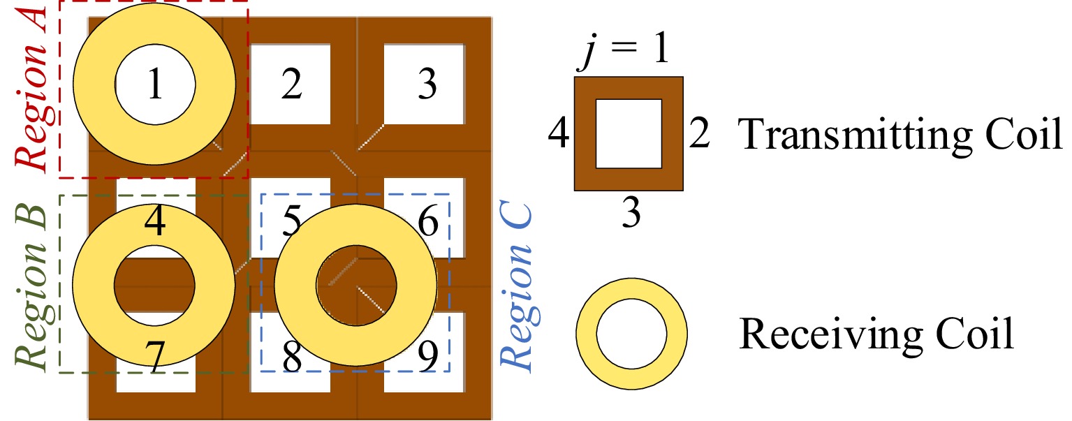
Figure 2.
Variation in the positions of the receiving coil.
It is not difficult to find that although direct splicing, the square coil can create a larger charging area with higher transmission efficiency. However, there are significant magnetic field fluctuations and zero and polarity flipping problems in this area. Therefore, it is not practical to directly apply it to charge the UAV in real-world situations. Improvements need to be made to the coupler. When the UAV moves above a square coil, of which the current direction is opposite to the receiving coil, it is necessary to switch the overall current direction of the transmitting coil to ensure that the current direction of the transmitting coil, which is located beneath the receiving coil, is always consistent with the receiving coil. At the same time is necessary to add a transition section to the transmitting coil to raise the lower value of the mutual inductance curve, so that when the UAV flies above the coupler, the mutual inductance between the couplers always remains in a relatively stable area.
Design of the judging coil
-
Based on the above analysis, a coupler structure as shown in Fig. 3a was designed. The 3 × 3 transmitter coupler designed in this paper includes three parts: the bottom ferrite, the middle transmitting coil, and the upper judging coil. The bottom ferrite is used to bundle magnetic field lines, increase magnetic field strength, and improve transmission efficiency[21]. The middle transmitting coil is the main coil, formed by splicing two layers of coils with opposite current flow directions. The upper judging coil has two functions in this paper. On the one hand, it serves as a compensation coil for the middle transmitting coil to compensate for mutual inductance fluctuations. On the other hand, the position of the UAV is located by it, and a signal is released to switch the conductive state of the circuit. The receiving coil is a circular coil installed on the UAV.
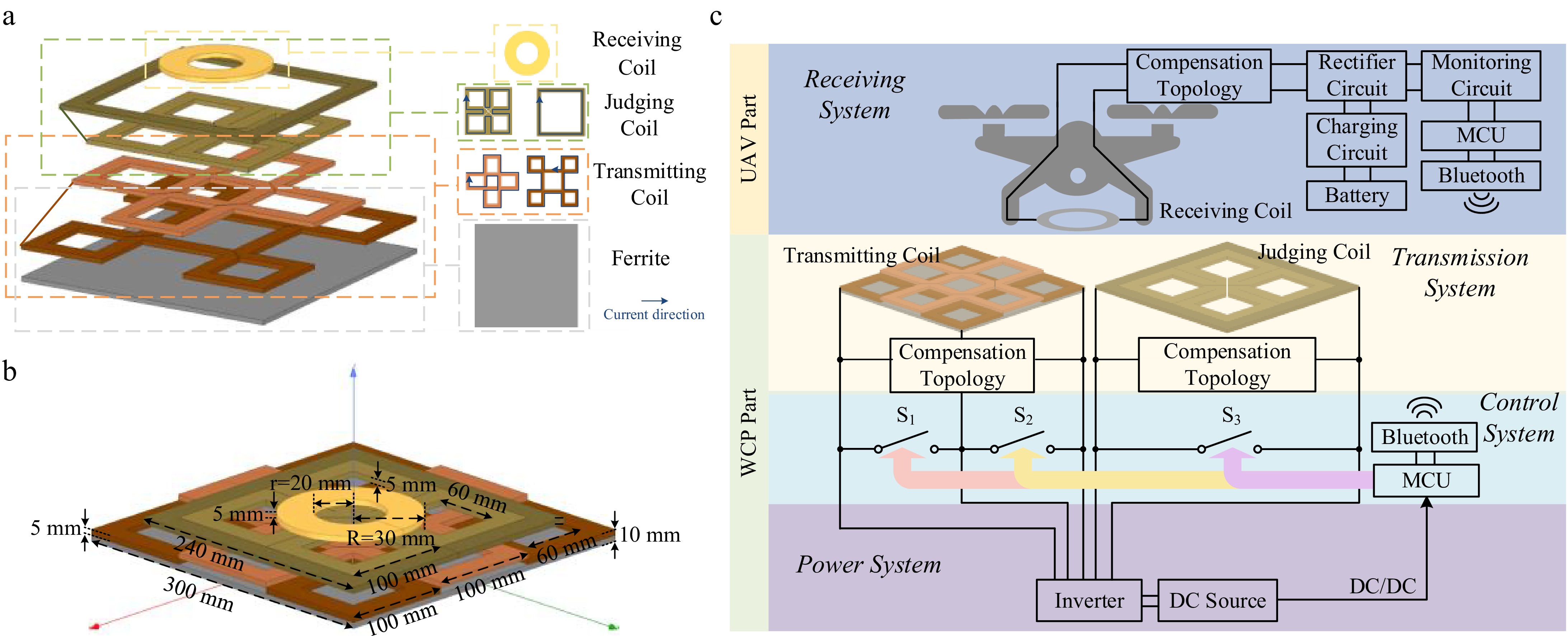
Figure 3.
(a) Overall structure of the couplers. (b) Dimensions of each part of the couplers. (c) System architecture diagram of the UAV charging system.
By the judging coil, the position of the UAV can be determined based on the charging efficiency. By adding control strategies, the system can be adaptively switched to the most suitable charging state for the UAV. Three charging states are mainly set in this paper: State 1 represents the forward conducting transmitting coil; State 2 represents the reverse conducting transmitting coil; and State 3 represents the conducting judging coil.
When the UAV is in the weak energy transmission area of the transmitting coil, the charging coil will spontaneously switch from the transmitting coil to the judging coil. Then the judging coil will play the role of the main charging coil. The overall structure and dimensions of each part of the coupler are shown in Fig. 3a and b. In this structure, the cross areas of the square coils in the transmitting coil are replaced by the central areas of the square coils in the judging coil.
-
The wireless charging system designed in this paper can be divided into the UAV part, which includes the Receiving System, and the WCP part, which includes the Transmission System, Control System, and Power System. The specific system components are depicted in Fig. 3c.
The circuit structure is shown in Fig. 4a. The DC input voltage, denoted as Uin, is transformed into the high-frequency AC input voltage US by four MOSFETs (D1−D4). C represents the filter capacitor for Uin. LT1 is the transmitting coil, LT2 is the judging coil, and LR is the receiving coil. S1−S5 refer to the switch tubes. The Microcontroller Unit (MCU) provides switch signals to the switching devices S1−S5 through the General Input/Output (GPIO) ports to control the charging states.
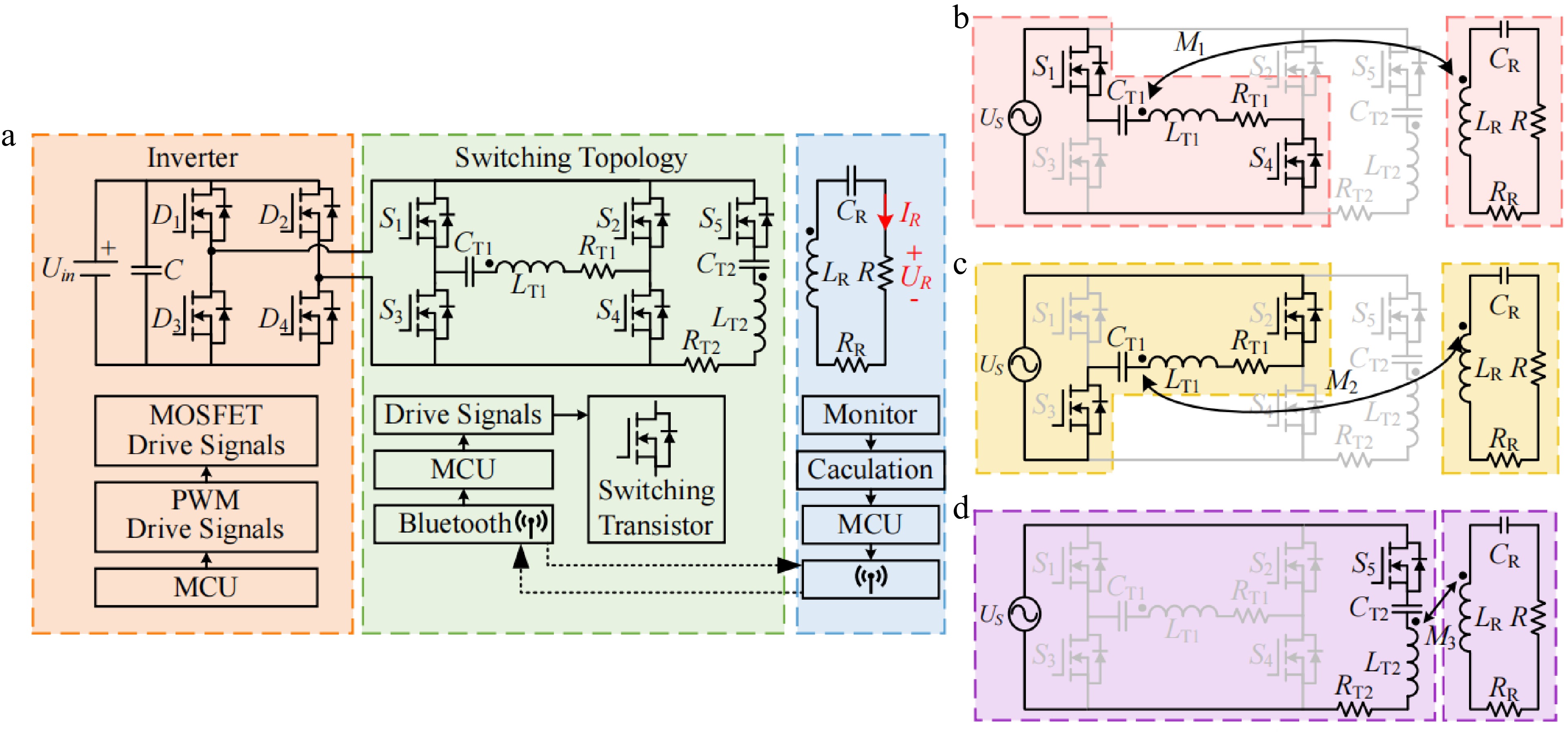
Figure 4.
System circuit structure. (a) Overall circuit diagram; (b) equivalent circuit diagram for State 1; (c) equivalent circuit diagram for State 2; (d) equivalent circuit diagram for State 3.
When in State 1, S1 and S4 are closed, and S2, S3, and S5 are open, the equivalent circuit diagram is shown in Fig. 4b. In this state, the judging coil is disconnected, and the transmitting coil is conducting forward. When in State 2, S2 and S3 are closed, while S1, S4, and S5 are open, as shown in Fig. 4c. In this state, the judging coil is disconnected and the transmitting coil conducts in the opposite direction. In State 3, S1−S4 are all open, and S5 is closed, as shown in Fig. 4d. In this state, the UAV is charged by the judging coil, and the transmitting coil is not conducted.
A state switching control technique is designed in this paper, based on the power transmission characteristics of the receiving coil at various points to achieve the aforesaid state switching. The strategy's flowchart is shown in Fig. 5.
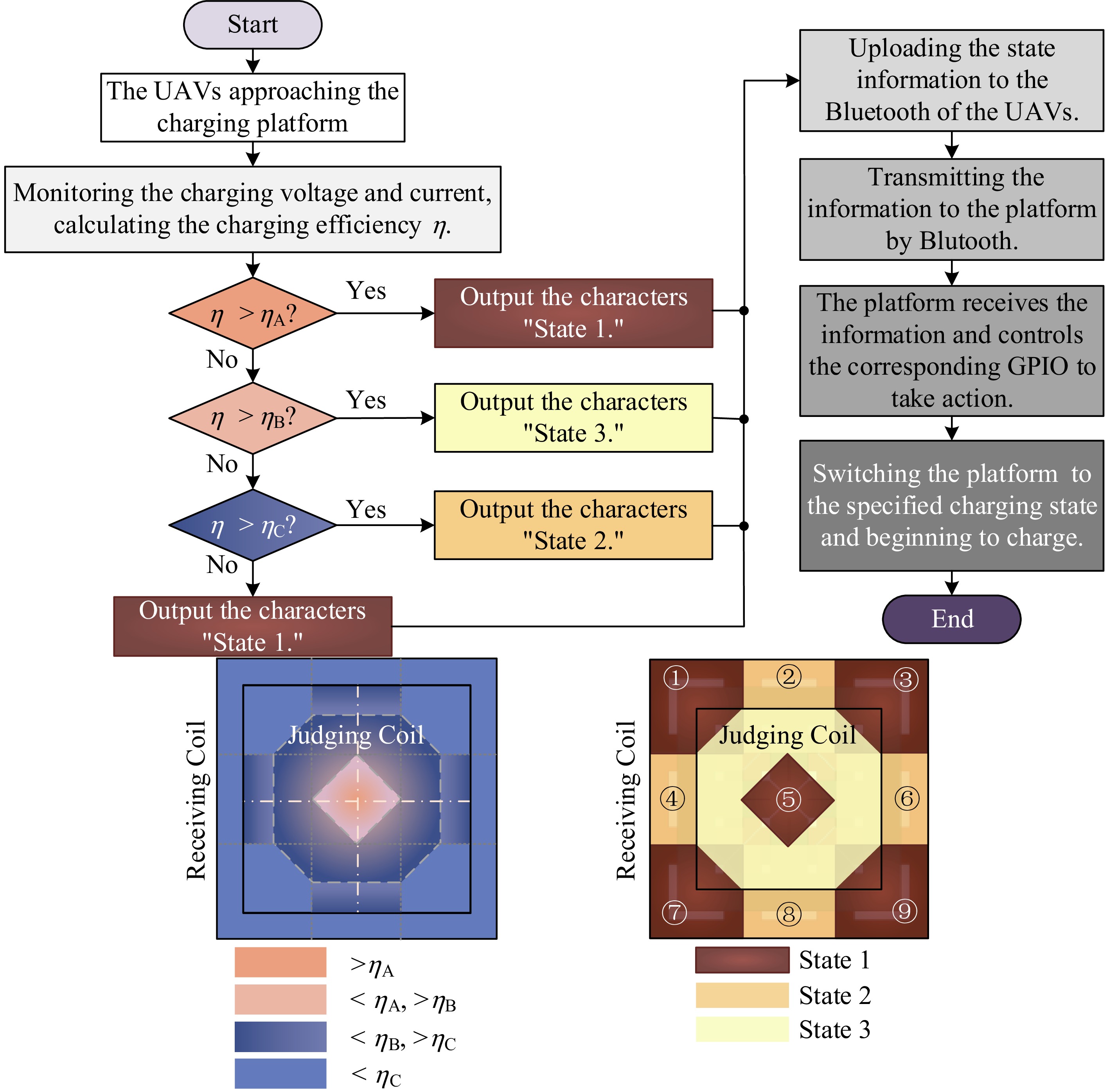
Figure 5.
Flowchart of the state switching control strategy.
The following steps comprise the UAV's adaptive switching charging process:
Step 1: Initialization of the system
First, switch on S5, turn off S1–S4, and initialize the charging platform. After that, the transmitting coil is unplugged, the judging coil becomes conductive, and it is always prepared to power the incoming UAV.
Step 2: Communication handshake
When the UAV enters communication range, Bluetooth pairing establishes bidirectional data transmission. Concurrently, the UAV lands on the WCP, entering standby mode.
Step 3: Positioning the UAV
Upon entering pre-charging mode via the judging coil's activation, the UAV's onboard MCU samples coil voltage and current to compute real-time input power. Using the preset output power reference, the MCU calculates instantaneous transfer efficiency. This efficiency value is then compared against preconfigured threshold levels. The comparative analysis determines: (1) the UAV's approximate lateral position relative to the transmitter coils, and (2) the required operating state for optimal power transfer. The MCU subsequently transmits these state requirements to the WCP via the established Bluetooth communication link.
Step 4: State switching and feedback
Upon receiving state transition commands from the UAV, the WCP activates the corresponding switching devices (S1−S4) to reconfigure the transmission circuit. This initiates the designated charging mode. During operation, the UAV continuously transmits status feedback to validate correct state execution. When charging concludes and the UAV exits communication range, the platform automatically resets: all switches except S5 are deactivated, the transmitter coil is de-energized, and the sensing coil re-enters detection standby. The system thus returns to its initialization state for subsequent charging cycles.
The setting of the relevant threshold efficiency depends on the position efficiency mapping database established by real-time acquisition of voltage/current data through the MCU at the unmanned aerial vehicle end in pre charging mode. Set ηA as the critical point for mode switching in Region A where the measured efficiency is greater than 85%; For the efficiency distribution of 65%−85% in Region B, take ηB as the critical point for mode switching; Region C takes ηC as the critical point for mode switching for the efficiency distribution of 45%−65%.
In summary, when the charging efficiency calculated by the monitoring circuit is greater than ηA, the onboard Bluetooth sends a status signal to the WCP. Upon receiving the signal, the MCU of the charging platform part sets the GPIO pins responsible for controlling S1 and S4 to output a high level, which leads the MOSFETs to be turned on. Simultaneously, it sets the GPIO pins controlling S2, S3, and S5 to output a low level, which leads the MOSFETs to be turned off. This action transitions the charging state to State 1. When ηB < η < ηA, given the influence of magnetic field strength, the efficiency of charging by the transmitting coil in the area where the UAVs are positioned is significantly lower than that of the judging coil. Therefore, S5 is turned on, while S1~S4 are turned off. This action transitions the charging state to State 3. When ηC < η < ηB, S2 and S3 should be turned on, and S1, S4, and S5 should be turned off. This causes the transmitting coil to be reversely conducted, which makes the current direction in the area match the receiving coil. Finally, when η < ηC, switching the platform to State 1 can achieve greater charging efficiency. If the UAV is far from the effective charging area of the WCP, the deviation is too large and is not considered.
-
To examine the validity of the theories, a model is built based on the structure presented in Fig. 3 by the use of the finite element simulation software, and the system parameters are detailed in Table 1, where Uin represents the DC input voltage; f is the operating frequency; LT1, LT2, LR, CT1, CT2, CR, NT1, NT2, NR represent the self-inductance values, compensation capacitor sizes, and the number of turns for the transmitting coil, judging coil, and receiving coil, respectively, with units in μH, nF, and turns; R is the equivalent load resistance. To avoid interference from other objective factors, such as coil self-inductance, on the results, the number of turns, NR, of the receiving coil is increased to increase the self-inductance of the receiving coil while ensuring that the coil size remains unchanged, so as to make the results more objective.
Table 1. System simulation parameters.
Parameter Value Parameter Value Uin 20 V LT1 2,395 μH f 86 kHz LT2 771 μH CT1 1.43 nF LR 787 μH CT2 4.44 nF CR 4.35 nF R 50 Ω NT1 35 NT2 25 NR 90 As shown in Fig. 6a, when the UAV is in the center area of the nine square coils of the transmitting coil, a larger magnetic field strength is obtained. However, when the UAV reaches the cross areas of the square coil edges, the magnetic field strength is shown as a significant decrease. When the UAV moves directly above the transmitting coil without adding a control strategy, there will be significant efficiency fluctuations. Through the compensation effect of the judging coil, when the UAV moves to the weak energy transmission area, the WCP undergoes coil switching, thereby lifting the magnetic field strength of the weak energy transmission area of the transmitting coil, improving the energy transfer ability between couplers, and making the mutual inductance change more stable during the offset.
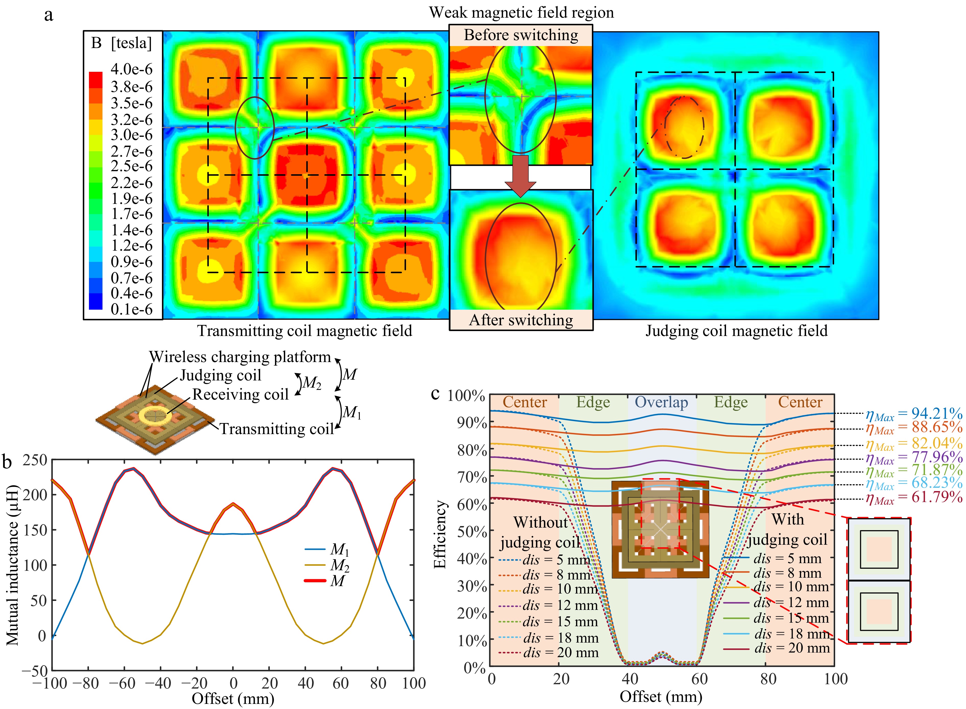
Figure 6.
(a) Compensation for magnetic field strength. (b) Mutual inductance between coils with offset. (c) Variation of the charging efficiency with offset at different heights.
Based on Fig. 4, a circuit simulation model is constructed to study the changes in charging efficiency of the coupler model designed in this paper. The changes of mutual inductance between coils during load offset are shown in Fig. 6b, where M1 represents the mutual inductance between the receiving coil and the transmitting coil when the judging coil is not intervened; M2 represents the mutual inductance between the receiving coil and the judging coil when the transmitting coil is not intervened; M represents the mutual inductance between the receiving coil and the WCP under the switching control strategy proposed in this paper. Obviously, as the offset process proceeds, both the judging coil and the transmitting coil will have a mutual inductance collapse zone with the transmitting coil, and when the control strategy intervenes, the original collapse zone will be quickly filled, which can effectively reduce the coverage area of the low mutual inductance area and increase the effective charging area range. When the receiving coil is located at different heights and deviates along the diagonal of the coupler, the result is shown in Fig. 6c, where dis is the longitudinal spacing between the transmitter coupler and the receiving coil.
The curves in Fig. 6b are mainly divided into two groups, which represent the efficiency changes with the offset before and after adding the judging coil and the control strategy. When the offset is small, the difference in efficiency before and after adding the judging coil is not significant. The offset occurs in the central area inside the square coil, where the magnetic field strength is relatively high and stable. As the offset increases, the UAV moves to the edge area of the square coil. The transmission efficiency between couplers without a judging coil will significantly decrease, while there will be a small fluctuation in transmission efficiency after adding a judging coil. When the UAV reaches the cross section of two coils, the efficiency without the judging coil is almost 0, while the coupler with the judging coil switches to another charging state, and the transmission efficiency rises to its peak again. When the UAV continues to move and reaches the edge area of adjacent transmitting coils, the transmission efficiency between couplers without the addition of the judging coil will rapidly increase with the offset, while the efficiency between couplers with the addition of the judging coil remains within a small range of wave motion. Finally, when the UAV flies into the central area of adjacent coils, the transmission efficiency between the couplers before and after adding the judging coil reaches its peak again. During the entire offset process, the peak charging efficiency of the UAV is 94.21%, and the average charging efficiency after adding a judging coil is 90.68%.
-
To verify the feasibility of the design method proposed in this paper, a test platform, as shown in Fig. 7a, was built.
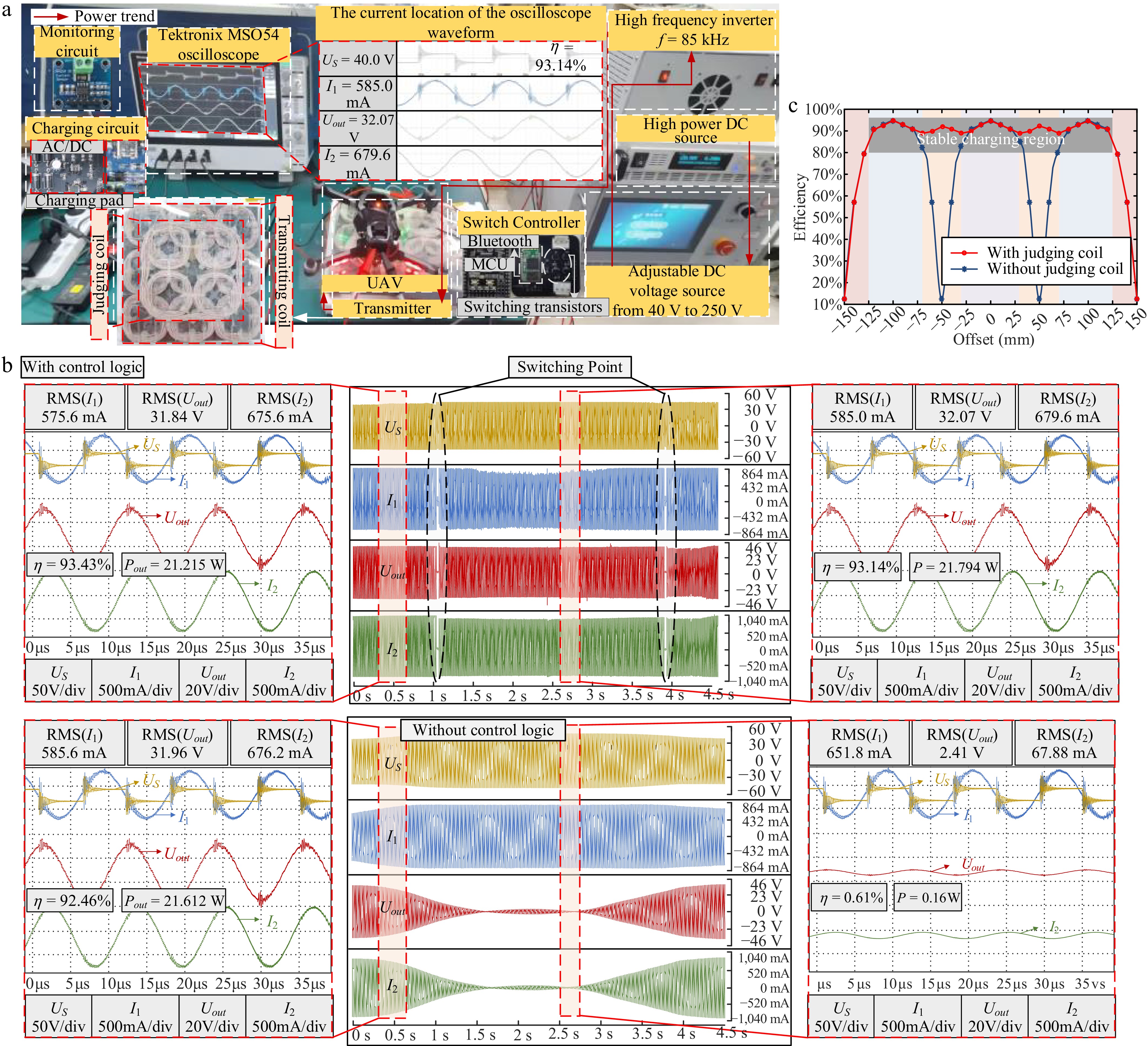
Figure 7.
(a) Experimental prototype. (b) Continuous and static waveforms of the oscilloscope before and after the control logic was added. (c) Changes in efficiency during a full offset.
The system is composed of a high power DC source, an adjustable DC source, a high frequency inverter, magnetic couplers, a switching controller, a charging circuit, a monitoring circuit, and a UAV. The transmitter coupler is situated above a 300 × 300 × 10 mm3 ferrite cuboid NCD LP9. Experimental parameters are kept consistent with the simulation parameters as outlined in Table 1. Waveforms of the input voltage (US), input current (I1), output voltage (Uout), and output current (I2) are recorded by a Tektronix MSO54 oscilloscope.
To ensure that the UAV does not have any impact on energy transmission due to changes in rotation or other angles, the shape of the receiving coil is limited to a circular coil. The magnetic field distribution under this coil structure is less affected by angle changes, which can effectively weaken the effects of rotation and other aspects. When the receiving coil of the UAV moves 5 mm above the transmitter coupler, the changes in US, I1, Uout, and I2 are shown in Fig. 7b. The charging efficiency of the transmitting coil as the main charging coil can reach 93.43%. After switching, the charging efficiency of the judging coil as the main charging coil can reach 93.14%, with little fluctuation before and after the switch. The overall energy transmission can be considered relatively stable. If the judging coil and the switching control strategy are not added, the charging efficiency of the UAV will be reduced from 92.26% to 0.61%, and energy transmission will be almost impossible to complete. According to experimental calculations, when the UAV moves to the edge area of the overall structure of the transmitter coupler, the efficiency will be significantly decreased. The stable and efficient effective charging area is in the range of (−125 mm, 125 mm), which accounts for 83% of the overall range of the coupler (−150 mm, 150 mm), as shown in Fig. 7c. The experimental conclusion shows that the composite coupler structure designed in this paper, supplemented by the corresponding switching control strategy, can increase the effective energy transmission area of the launch platform while ensuring high transmission efficiency, and show good horizontal misalignment tolerance capability.
The coupler designed in this paper is compared with the existing research results in Table 2 in terms of charging efficiency, effective range, and horizontal misalignment tolerance. When solving the misalignment tolerance problem of wireless charging for drones, traditional solutions such as passive array coils require the deployment of multiple unit coils and independent compensation networks, which are bulky and rely on parameter optimization and large-scale finite element simulation, resulting in heavy computational burden and high hardware redundancy. In contrast, the reconfigurable array scheme proposed in this paper simplifies the structure of the transmitting coil and the judging coil, and uses MOSFET switches to achieve three state dynamic switching, reducing hardware complexity. It also achieves real-time positioning through Bluetooth communication, significantly improving dynamic adaptability. In terms of efficiency and performance, the reconfigurable scheme proposed in this paper achieves an alignment efficiency of 93.43%, and maintains 93.14% even after offset switching, with low efficiency fluctuations and solving the polarity reversal problem of traditional arrays. In terms of anti offset capability, the reconfigurable scheme in this paper supports ± 125 mm offset through omnidirectional design.
Table 2. Comparison between the coupler in this paper and existing research results.
Ref. ηDC-DC Coverage Misalignment tolerance Simplicity Comprehensive This paper 89.28% 83% $\star \star \star $ $\star \star $ $\star \star \star $ [10] 87.1% 50% $\star $ $\star \star \star $ $\star $ [25] 90.5% 44% $\star \star \star $ $\star \star \star $ $\star \star $ [26] 84.9% 60% $\star \star $ $\star \star \star $ $\star \star $ [27] 90.1% 67% $\star \star \star $ $\star \star \star $ $\star \star \star $ [28] 93.1% 40% $\star \star \star $ $\star \star \star $ $\star \star $ [29] 84.6% 67% $\star \star \star $ $\star $ $\star \star $ * The higher the number of '$ \star $', the better the performance. -
The coupler designed in this paper is based on the coil recombination. The reconfigurable feature is a prominent feature of this design method. This is mainly reflected in the reconstruction of coupler structure in the scenario of single-input and single-output (SISO), as well as the modular configuration of couplers in the scenario of multiple-input and multiple-output (MIMO).
Simply put, the SISO scenario is for a single UAV. Based on the spatial structure of the charging area and the size of the UAV, the structural form of the transmitter coupler can be reconstructed and designed, and the charging area can be subdivided into micro segments to meet the requirements of various area shapes. The 3 × 3 transmitter coupler designed and analyzed in this paper is only a special structure. According to user needs, the 2 × 2 transmitter coupler, the 3 × 5 transmitter coupler, and even some irregular emission coupler structures are also easy to implement, as shown in Fig. 8a.
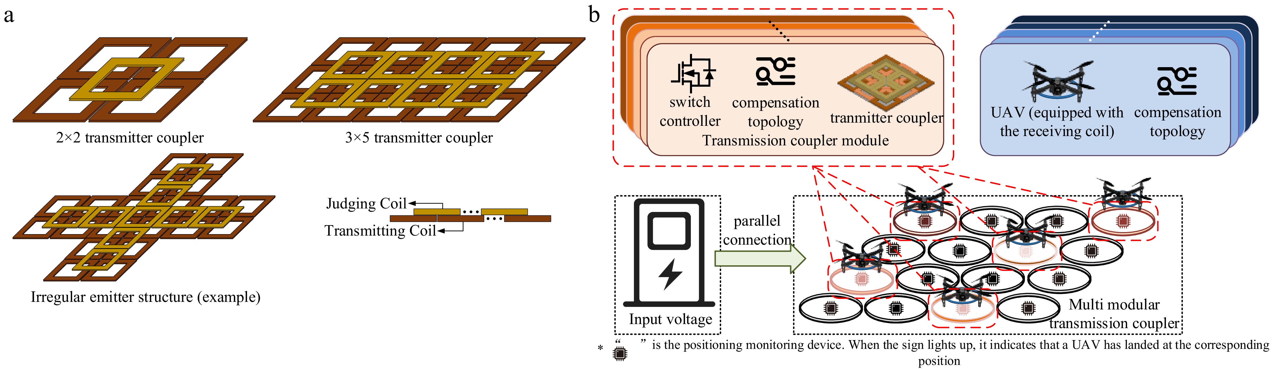
Figure 8.
(a) Examples of the coupler reconstruction configuration for the SISO ccenario. (b) Coupler reconstruction configuration scheme in the MIMO scenario.
After completing the simple SISO scenario coupler reconstruction configuration, it is necessary to consider the situation of multiple UAVs charging simultaneously. By modularizing the coupler configuration designed for the SISO scenario, adding simple positioning monitoring devices, conducting the corresponding modules based on the landing position of the UAV, and then using the coupler switching control method proposed in this paper, an efficient horizontal misalignment tolerance WPT system in the MIMO scenario can be achieved. Simply put, taking TMS320F28335 as an example, the chip has 88 GPIO ports. According to the control method in this paper, two GPIO ports are used to control one transmitter coupler. In theory, up to 44 transmitter couplers can be controlled simultaneously for conduction, which means charging 44 UAVs simultaneously. When there is no UAV flying in and the transmitter coupler of a single module is unloaded, the coupler can be controlled to turn off to reduce the power loss. When the positioning monitoring device recognizes that a UAV is driving in, the corresponding module will be connected, and the charging strategy designed in this paper will be used for power supply, as shown in Fig. 8b. However, this part is not the focus of this paper, so it will not be elaborated on here.
This work was supported in part by the National Nature Science Youth Foundation of China (Grant No. 51807095), in part by the '333 Engineering' Research Project of Jiangsu Province (Grant No. 3-16-292), in part by the Natural Science Foundation of the Higher Education Institutions of Jiangsu Province (Grant No. 22KJB470021), and in part by the Postgraduate Research & Practice Innovation Program of Jiangsu Province (Grant No. SJCX24-0656).
-
The authors confirm their contribution to the paper as follows: Study conception and design: Wang W, Li K, Duan M; Data collection: Wang W, Li K, Xu C; Analysis and interpretation of results: Wang W, Li K, Sheng S; Draft manuscript preparation: Wang W, Li K, Lu Z. All authors reviewed the results and approved the final version of the manuscript.
-
Data sharing not applicable to this article as no datasets were generated or analyzed during the current study.
-
The authors declare that they have no conflict of interest.
- Copyright: © 2025 by the author(s). Published by Maximum Academic Press, Fayetteville, GA. This article is an open access article distributed under Creative Commons Attribution License (CC BY 4.0), visit https://creativecommons.org/licenses/by/4.0/.
-
About this article
Cite this article
Wang W, Li K, Duan M, Xu C, Sheng S, et al. 2025. A reconfigurable wireless charging optimization scheme for UAVs with horizontal misalignment tolerance. Wireless Power Transfer 12: e029 doi: 10.48130/wpt-0025-0028 

A reconfigurable wireless charging optimization scheme for UAVs with horizontal misalignment tolerance
- Received: 05 April 2025
- Revised: 20 July 2025
- Accepted: 31 July 2025
- Published online: 15 November 2025
Abstract: Unmanned aerial vehicles (UAVs) are widely used by civilians, the military, and other fields. To ensure the autonomous working ability, high levels of charging convenience are required. Wireless power transfer (WPT) is an excellent solution to the problem due to its convenient charging characteristics. However, when there is a deviation between the UAV and the charging platform, the UAV often cannot be in the optimal charging area. Low efficiency or power fluctuation will occur, which may cause damage to the battery. This paper proposes a reconfigurable and efficient WPT system with horizontal misalignment tolerance to solve the issue of stable and efficient energy transmission between the UAV and the charging platform. The accuracy of the structure is verified through simulation analysis and experimental prototypes. The results show that the WPT system designed in this paper can provide a charging efficiency of more than 90%, and the coverage area of a stable charging area reach more than 80%, under the condition of short-distance transmission. Moreover, with its reconfigurable characteristics, the coupler arrangement can be freely designed according to the required charging scene. This study provides an effective solution to the problem of omni-directional error tolerance in UAV wireless charging.