










-
With the continuous advancement of flight control systems, sensor integration, and autonomous navigation technologies[1], multirotor unmanned aerial vehicles (UAVs) have been widely applied in both civil and military domains. Owing to their compact structure, low cost, and capability for vertical takeoff and landing (VTOL), these platforms have demonstrated distinct advantages in missions such as logistics delivery, industrial inspection, agricultural protection, and emergency rescue operations[2−4]. However, as the demands for higher payload capacity and extended endurance increase, the aerodynamic performance of traditional configurations has gradually become a critical limiting factor. In single-layer configurations, the rotor diameter is constrained by the vehicle's overall size, restricting thrust generation per unit power. Although coaxial configurations can effectively increase the total rotor disk area within a compact layout, the strong wake interference between the upper and lower rotors leads to a significant reduction in system aerodynamic efficiency[5−8]. Therefore, achieving enhanced aerodynamic efficiency while maintaining a compact airframe remains a major challenge in the overall design of multirotor UAVs[9].
In the study of aerodynamic interference among multirotor systems, numerous investigations have been conducted on single-layer configurations. Herz et al.[10,11] revealed, through wind-tunnel and full-scale experiments, the influence of fuselage blockage, rotor rotation direction, and layout arrangement on the aerodynamic characteristics. Hwang et al.[12] analyzed the effects of rotor-rotor and rotor-fuselage interactions on the overall performance of multirotor UAVs. Atte et al.[13,14] demonstrated that rotor spacing and arrangement pattern are key factors determining aerodynamic performance, while Yoon et al.[15] further confirmed the sensitivity of performance to configuration differences. For coaxial configurations, the lower rotor operates within the wake of the upper rotor, and the blade–vortex interaction (BVI) between the two rotors leads to significant power losses[16−18]. Moreover, such BVI effects have a pronounced impact on aeroacoustic characteristics[19,20]. Singh & Venkatesan[21] found that thrust degradation is closely correlated with the rotational speed ratio and axial spacing between rotors. Stokkermans et al.[22] reported that non-coplanar rotor arrangements can cause severe performance degradation of the downstream rotor when lift surfaces overlap. Jacobellis et al.[23] quantitatively analyzed variations in thrust and power with respect to azimuthal offset and axial separation. Shukla & Komerath[24] further identified an anomalous phenomenon in which the upper rotor of a coaxial pair may outperform a single rotor under certain conditions, attributing this to a viscous vortex-recovery mechanism[25]. Existing research has primarily focused on the aerodynamic interference mechanisms of general multirotor systems, while systematic configuration design and performance comparisons specific to hexacopter platforms remain limited. Experimental efforts have mostly been confined to isolated rotors, partial rotor arrays, or simplified prototypes. Consequently, the potential and engineering feasibility of implementing a staggered configuration in a hexacopter platform have yet to be thoroughly explored.
In recent years, unconventional configurations have attracted increasing attention. Stokkermans et al.[22] investigated how propeller interactions in side-by-side and tandem arrangements affect performance metrics such as thrust, power, in-plane forces, and out-of-plane moments, as well as how these performance variations depend on axial and lateral propeller spacing. Johnson et al.[26] and Silva et al.[27] proposed various eVTOL aircraft concepts with different layouts. The work by Johnson et al. emphasized the effects of rotor–rotor interactions on vehicle performance, while Silva's study focused on aircraft design missions under specified payload conditions. Ramasamy[28] analyzed the aerodynamic interference between two staggered rotors in hover using blade element momentum theory and a series of experiments, revealing the performance development potential of staggered rotor systems. Cai et al.[29,30] experimentally compared the thrust and efficiency characteristics of tandem staggered dual rotors. Their results showed that performance is highly dependent on advance ratio and separation distance, with significant performance degradation observed under certain configurations. Zanotti & Algarotti[31] performed particle image velocimetry (PIV) measurements on overlapping co-rotating propeller models to evaluate the influence of aerodynamic interactions on propeller performance and flow field. Brazinskas et al.[32] conducted performance measurements on various overlapping configurations under a system torque-balanced mode using a dedicated test rig. By comparing with an isolated dual-rotor system, the interference factors were revealed and further compared with momentum theory predictions. Xu et al.[33] numerically analyzed the effects of parameters such as separation distance, blade spacing, and rotation direction on the interference flow field between overlapping rotors. Otsuka & Nagatani[9] proposed a staggered arrangement method based on rotor disk overlapping and experimentally verified its potential in reducing the projected area. In previous work, the authors conducted experimental studies on the hover performance of small-scale staggered rotor systems[34,35], and the results indicated that the radial distance between rotors exerts a significant influence on the system aerodynamic performance. Although the above studies have laid an important foundation for the design and analysis of staggered rotor systems, most existing work focuses on rotor pair configurations and has not extended the staggered layout to full-scale hexacopter platforms for numerical investigation. Meanwhile, the comprehensive performance advantages of the staggered configuration over conventional single-layer and coaxial configurations have not been systematically compared. Furthermore, most previous studies adopted either experimental or numerical simulation alone, making it difficult to achieve both in-depth revelation of flow-field mechanisms and effective validation of engineering practicality.
Against the research background and the aforementioned limitations, this paper proposes an innovative dual-layer radially staggered hexacopter configuration. Based on the upper-lower layered rotor arrangement, a radial staggering design is adopted, allowing larger-diameter rotors to be installed without increasing the fuselage size. This configuration effectively mitigates rotor–rotor aerodynamic interference and breaks the performance bottlenecks of conventional layouts. This work extends the staggered layout from dual-rotor systems to a complete hexacopter platform. Under the constraint of uniform fuselage and arm dimensions, the hover performance, flow-field evolution mechanisms, and unsteady load characteristics of the novel staggered configuration are systematically compared with those of conventional single-layer and coaxial configurations at two rotor scales (small and large). A combined research approach of high-fidelity CFD numerical simulation and prototype flight testing is employed, which not only reveals the inherent flow-field mechanisms of wake development and interference suppression, but also verifies the flight stability and control compatibility of the proposed configuration. This study provides a novel and efficient aerodynamic layout scheme for the design of multirotor aircraft applied in confined-space and high-payload mission scenarios.
The structure of this paper is organized as shown in Fig 1. Materials and methods introduces the configuration design and numerical simulation methods. Results analyzes the aerodynamic characteristics and flow-field evolution mechanisms under both small-rotor and large-rotor conditions. Experimental verification presents the prototype flight tests and verifies the feasibility of the proposed configuration. Finally, Conclusions summarizes the main innovations and conclusions of the study.
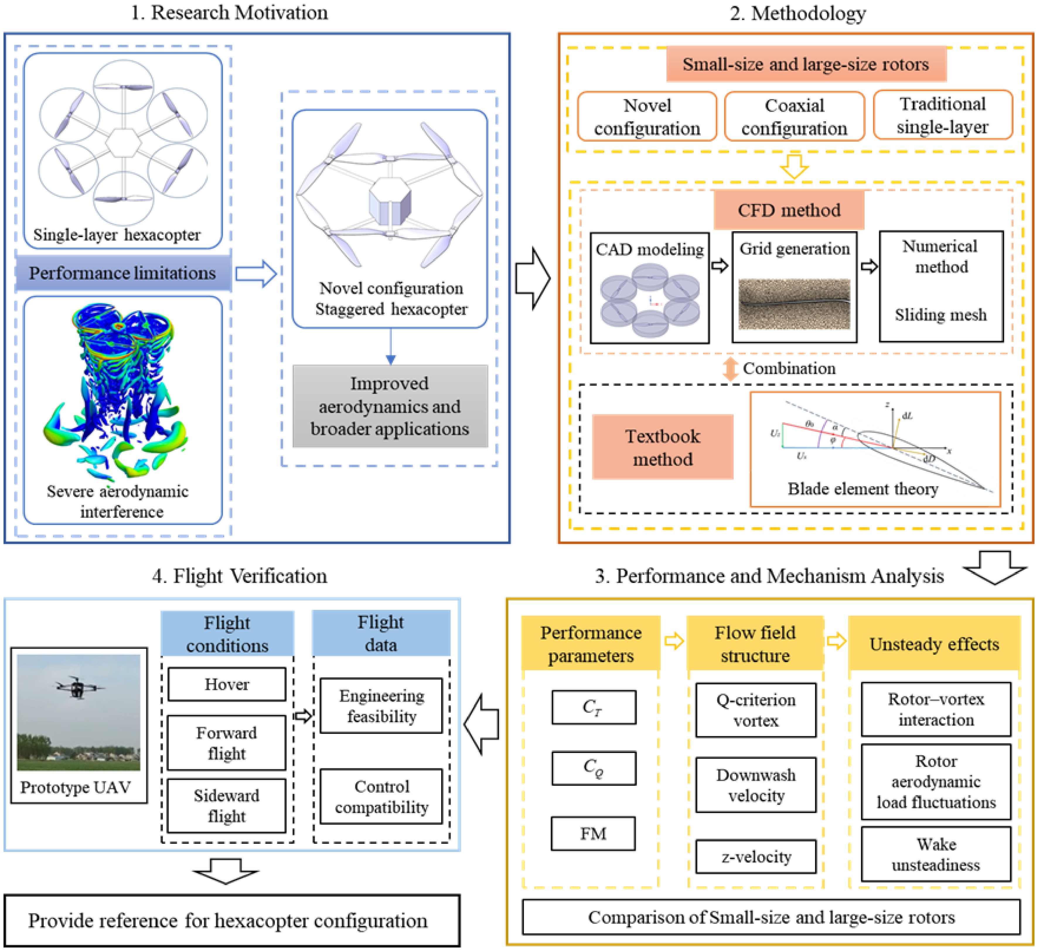
Figure 1.
Research logical relationship diagram.
-
In this study, the T-MOTOR 1855 all-in-one carbon fiber rotor was adopted. It is a two-bladed propeller with a blade diameter D = 457.2 mm (18 inches) and a pitch P = 139.7 mm (5.5 inches). The main geometric parameters were obtained through physical measurement and 3D model inversion, as shown in Fig 2.
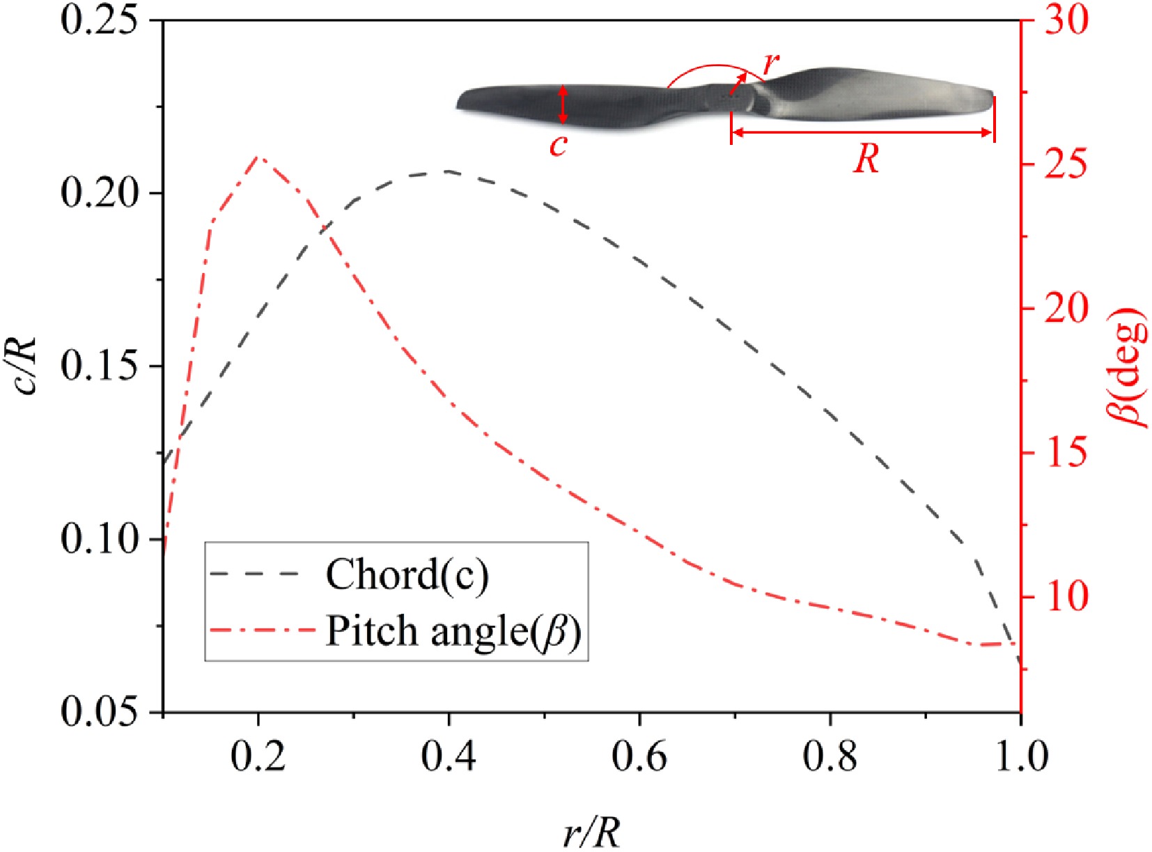
Figure 2.
Plot of propeller's chord (c) and pitch angle (β) distribution of the T-MOTOR 1855 propeller.
As shown in Fig 3, this study focuses on the configuration layout of an open-frame hexacopter, considering three configuration schemes: the traditional single-layer configuration, the coaxial configuration, and the novel dual-layer staggered configuration. To systematically compare the aerodynamic performance among different layouts, two rotor size schemes were designed: a small rotor with a radius of R1 = 230 mm and a large rotor with a radius of R2 = 430 mm. The two rotor sizes share identical geometric features, differing only in scale. In all configurations, the fuselage and arm dimensions remain the same. These dimensions are determined based on the minimum layout space formed by six tangent rotor disks in the traditional single-layer hexacopter configuration (Fig. 3a), ensuring a compact overall arrangement. When the rotor radius increases, the traditional single-layer configuration can no longer accommodate all rotors within the predefined arm length without overlap; therefore, the large-rotor size is applied only to the coaxial and dual-layer staggered configurations. The radius of the large rotor, R2 = 430 mm, is determined by the maximum geometric space that allows three pairs of coaxial rotor disks to be tangent within the layout (Fig. 3b). This selection ensures the consistency of airframe geometric parameters across different configurations, enabling a systematic comparison of their aerodynamic performance.
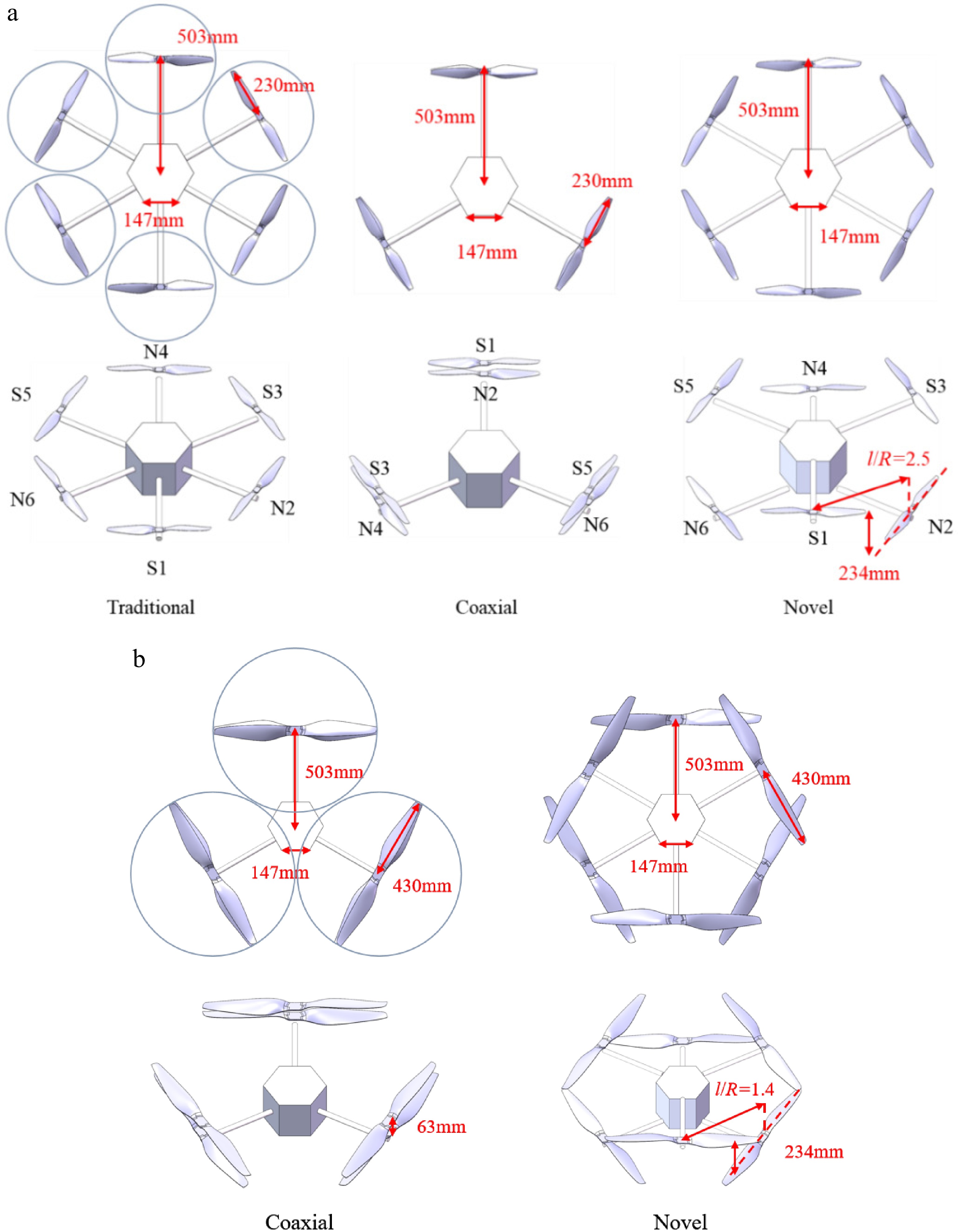
Figure 3.
Different hexacopter configurations. (a) Small-sized rotor. (b) Large-sized rotor.
Domain decomposition and computational mesh
-
Figure 4a illustrates the schematic of the computational domain for the traditional single-layer configuration, with all other configurations adopting the same domain dimensions and boundary conditions. The computational domain consists of two regions: a stationary region and a rotating region. The stationary region is a rectangular cuboid with a height of 15R (where R is the rotor radius) and both length and width of 10R. The rotating region is a cylindrical zone enclosing the rotor, with a diameter of 2.2R and a thickness of 0.4R. Data exchange between the two regions is achieved through an Interface boundary, ensuring flow-field continuity between the stationary and rotating meshes. To accurately capture the local flow features around the UAV, a Body of Influence (BOI) refinement zone is applied near the fuselage and rotors. This approach allows for local mesh refinement in targeted regions without subdividing the overall computational domain, thereby improving near-field flow resolution. For the stationary domain, the boundary conditions are set as follows: the inlet face is defined as a velocity inlet with a constant turbulence intensity of 1% to simulate the flow condition of the UAV in an outdoor windless environment; the outlet face is defined as a pressure outlet with a relative static pressure of 0 Pa (i.e., ambient atmospheric pressure); the four surrounding faces of the cuboid are defined as free-slip walls; and the rotor surfaces enclosed by the rotating fluid zone are set as no-slip walls. Air is selected as the fluid medium, and the temperature is set to 25 °C. The rotor speed is set to 3,000 rpm, corresponding to the typical hover condition used in both the experiments and numerical simulations.
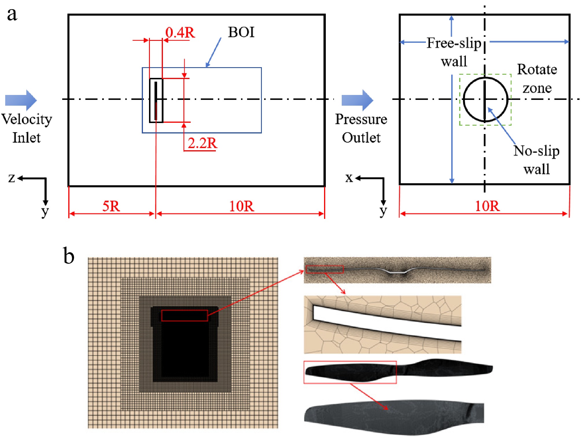
Figure 4.
Computational domain and mesh partitioning. (a) Computational domain and boundary conditions; (b) Computational mesh.
Figure 4b presents the cross-sectional mesh distribution of the traditional single-layer configuration. To balance computational accuracy and efficiency, polyhedral meshes are used in the rotating region, while trimmed meshes are applied in the stationary region, with the two connected through an unstructured interface. The total number of mesh cells for this configuration is approximately 14 million, including about 10 million in the rotating region and 4 million in the stationary region. The other configurations maintain the same mesh resolution. To accurately resolve the boundary-layer flow near the rotor surfaces, 20 layers of prism (inflation) meshes are applied on the blade surfaces, ensuring y+ < 1, which satisfies the near-wall resolution requirements of the turbulence model.
Numerical method
-
In this study, the rotor speed is set to 3,000 rpm, corresponding to a blade-tip Mach number below 0.3, allowing the airflow to be treated as incompressible. The numerical simulations solve the Reynolds-Averaged Navier–Stokes (RANS) equations using the finite volume method (FVM). Considering both accuracy and computational efficiency, the sliding mesh approach is employed to capture the unsteady wake characteristics while enabling a comparative analysis of the aerodynamic performance among the different UAV configurations. Unsteady numerical simulations were conducted on rotors of different configurations for 15 full rotational revolutions. After sufficient iterations over rotational periods, the fluctuations in aerodynamic load amplitude tend to stabilize, ensuring fully converged computational results. The time step is defined as the time corresponding to a 2° rotation of the rotor, namely 180 time steps per revolution. At a rotational speed of 3,000 rpm, the corresponding time step is approximately 0.00011 s. This setup allows for precise capture of the flow-field structure and periodic load fluctuations, guaranteeing accurate resolution of the relevant flow features[36].
Since the flow satisfies the incompressible assumption, a pressure-based solver is used, and pressure correction is applied to enforce mass conservation in the velocity field. The Reynolds stress term in the RANS equations requires closure with a turbulence model, and the Shear Stress Transport (SST) k-ω model is adopted in this paper[37−39]. As a two-equation eddy-viscosity model, it integrates the free-stream insensitivity of the k-ε model in the far-field free-stream region to prevent divergence of the pure k-ω model in free streams, while preserving the accuracy of the k-ω model in the near-wall region, thus providing reliable support for mechanism analyses such as wake convergence height and induced velocity uniformity[40]. The numerical solution employs a coupled velocity-pressure algorithm (coupled scheme) to simultaneously iterate the continuity and momentum equations, thus accelerating convergence. A second-order implicit time-stepping scheme is used to ensure the accuracy and reliability of the unsteady simulation results[41].
As a URANS-type turbulence model, the SST k-ω model introduces numerical dissipation through its time-averaged treatment of turbulence and has certain limitations in resolving large-scale flow separation and vortex shedding. Although URANS involves approximations in characterizing transient loads and wake details, it exhibits sufficient reliability in predicting the overall aerodynamic performance of rotors (including thrust, torque, hover figure of merit [FM], etc.) and the development of primary flow fields, and can accurately reflect the relative differences and evolutionary trends of aerodynamic performance and flow characteristics under different multirotor configurations. Furthermore, this model has been widely employed in investigations of the aerodynamic performance of small-scale propellers[42,43].
Grid independence study
-
To ensure the validity of the proposed method and the reliability of the numerical simulation results, this section compares the simulation results of a single rotor with experimental data. The grid count of the rotating domain for the single rotor is approximately 1.72 × 10⁶, and that of the stationary domain is about 2.05 × 10⁶. The thrust coefficient (CT) and torque coefficient (CQ) are calculated respectively, and the credibility of the grid and numerical method is evaluated by monitoring the relative errors between the simulated and experimental values of CT and CQ. The sampling strategy adopts the average results of the last three revolutions (i.e., the 13th to 15th revolutions) of the numerical simulation, and this sampling strategy is also applied to all subsequent results and analyses. The comparison between the simulation results and experimental data is shown in Table 1, with a maximum relative error of less than 5.78%, which verifies the effectiveness of the proposed method. Meanwhile, the relationships between the thrust coefficient, torque coefficient, and rotational speed of the single rotor are quantitatively validated, as illustrated in Fig 5. The maximum error between the CFD-calculated thrust coefficient and the experimental data is less than 8%, and the maximum error of the torque coefficient is less than 5%, further enhancing the credibility of the CFD method.
Table 1. Comparison of simulation and experimental results.
Experiment Simulation Relative error (%) CT-isolated rotor (10−2) 1.142 1.076 5.78 CQ-isolated rotor (10−3) 1.754 1.7938 2.27 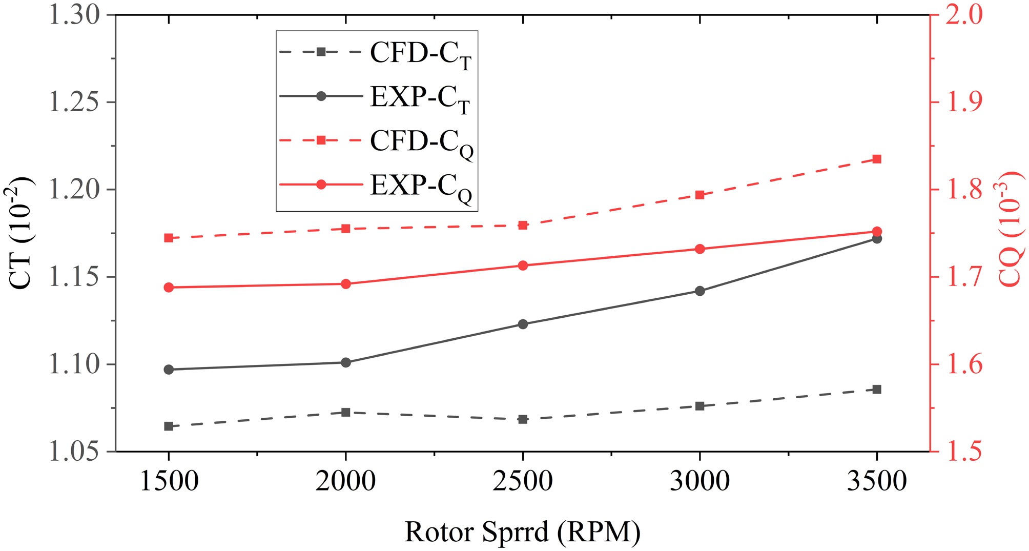
Figure 5.
Validation of thrust and torque coefficients for a single rotor.
Furthermore, a grid sensitivity analysis was performed in this study. The thrust and torque of a single rotor at different rotational speeds were calculated. The results are presented in Table 2, and the computational errors for both medium-density and fine-density grids are below 5%.
Table 2. Calculated results at different rotational speeds of the single rotor.
Rotational speeds 157.1 rad/s 209.4 rad/s 261.8 rad/s 314.2 rad/s 366.5 rad/s Number of grids Medium grids CT (10−2) 1.065 1.073 1.069 1.076 1.086 Rotor domain: 1.72 × 10⁶; Stationary domain 2.05 × 10⁶ Fine grids CT (10−2) 1.060 1.075 1.079 1.076 1.092 Rotor domain: 3.49 × 10⁶; Stationary domain 5.24 × 10⁶ Relative error (%) 0.472 0.186 0.927 0 0.549 / Medium grids CQ (10−3) 1.745 1.755 1.759 1.794 1.835 / Fine grids CQ (10−3) 1.682 1.701 1.712 1.749 1.754 / Relative error (%) 3.746 3.175 2.745 2.573 4.618 / Considering the complex rotor–rotor and rotor–fuselage interactions involved in this study, grid convergence verification was further conducted on the complete hexacopter system to ensure that the analyzed interference effects are not affected by grid resolution. For the novel staggered hexacopter configuration, the thrust and torque of each rotor were compared between medium-density and fine-density grids. The results are shown in Table 3, where the computational errors of each rotor under different grid densities are all below 5%, verifying that the grid resolution used in this work meets the computational requirements.
Table 3. Calculated results for each rotor of the complete hexacopter system.
Rotor # S1 S3 S5 N2 N4 N6 Number of grids Medium grids CT (10−2) 1.059 1.059 1.058 1.064 1.065 1.065 Rotor domain: 1.19 × 10⁷; Stationary domain: 4.02 × 10⁶ Fine grids CT (10−2) 1.081 1.082 1.082 1.089 1.089 1.087 Rotor domain: 2.14 × 10⁷; Stationary domain: 5.24 × 10⁶ Relative error (%) 2.035 2.126 2.218 2.296 2.204 2.024 Medium grids CQ (10−3) 1.843 1.850 1.843 1.862 1.867 1.869 Fine grids CQ (10−3) 1.787 1.786 1.779 1.789 1.801 1.803 Relative error (%) 3.134 3.583 3.598 4.081 3.665 3.661 Performance metrics
-
The thrust and torque of the isolated rotor and each rotor in the three configurations were calculated using the thrust coefficient in Eq. (1) and the torque coefficient in Eq. (2), respectively. The Figure of Merit (FM) for the isolated rotor and each rotor in the three hexacopter configurations was computed using Eq. (3)[44]. For the novel and traditional hexacopter configurations, the system-level FM was taken as the arithmetic mean of the FM values of all rotors in the configuration. The coaxial hexacopter can be regarded as consisting of three coaxial rotor pairs, and the FM of each coaxial unit was calculated using Eq. (4) proposed by Leishman & Syal[45]. The system-level FM of the coaxial configuration is thus obtained by taking the arithmetic mean of the FM values of all coaxial units. Based on the above FM definitions, the hover performance of different configurations and the individual rotors within each configuration can be quantitatively compared:
$ {C}_{T}=\dfrac{T}{\rho {({\Omega }R)}^{2}A} $ (1) $ {C}_{{Q}}=\dfrac{{Q}}{\rho {({\Omega }R)}^{2}{R}A} $ (2) $ \text{FM}=\dfrac{{C}_{T}{}^{\frac{3}{2}}}{\sqrt{2}{C}_{Q}} $ (3) $ \text{FM}=\dfrac{{C}_{T}{{{}_{{{}_{\text{u}}}}}}^{\frac{3}{2}}+{C}_{T}{{{}_{{{}_{\text{l}}}}}}^{\frac{3}{2}}}{\sqrt{2}({C}_{Q}{}_{{{}_{\text{u}}}}+{C}_{Q}{}_{{{}_{\text{l}}}})} $ (4) where
$ \rho $ $ A=\pi {R}^{2} $ $ \mathit{\Omega } $ $ {C}_{T}{}_{{{}_{\text{u}}}} $ $ {C}_{Q}{}_{{{}_{\text{u}}}} $ $ {C}_{T}{}_{{{}_{\text{l}}}} $ $ {C}_{Q}{}_{{{}_{\text{l}}}} $ -
Figure 6 compares the aerodynamic characteristics of the three configurations. As shown in Fig. 6a and b, the thrust generated by each rotor in the traditional single-layer configuration is relatively uniform, slightly lower than that of the new configuration, and higher than that of the lower rotor in the coaxial system. In the coaxial configuration, the upper rotor consistently produces more thrust than the lower rotor, and the thrust variation across rotors is small. The new staggered configuration achieves the highest overall thrust, with the lower rotors producing slightly more thrust than the upper rotors. Overall, the total thrust of the new configuration is approximately equal to that of the traditional configuration, and about 16.4% higher than that of the coaxial configuration, indicating superior aerodynamic performance in hover. Figure 6c shows the torque distribution of each configuration. Compared with thrust, the differences in torque are smaller. In the single-layer configuration, the torque values of all rotors are nearly identical. In the coaxial configuration, the upper rotor exhibits slightly higher torque than the lower rotor, and both are marginally higher than those of the single-layer configuration. In the new configuration, the torque of the lower rotor is slightly higher than that of the upper rotor. Figure 6d presents the FM distribution of each rotor. The results show that the new configuration achieves the highest overall FM values, with the smallest variation among rotors. Both the single-layer and coaxial configurations exhibit noticeable fluctuations, and the FM of the lower rotor in the coaxial configuration is significantly lower than that of the upper rotor and the single-layer case, indicating a marked performance deterioration of the lower rotor due to interference. Further evidence is shown in Fig. 6e, where the system-level FM indicates that the coaxial configuration has the lowest hover efficiency, the single-layer configuration performs slightly better, and the new configuration achieves the highest overall FM, representing an improvement of approximately 21.2% over the coaxial configuration.
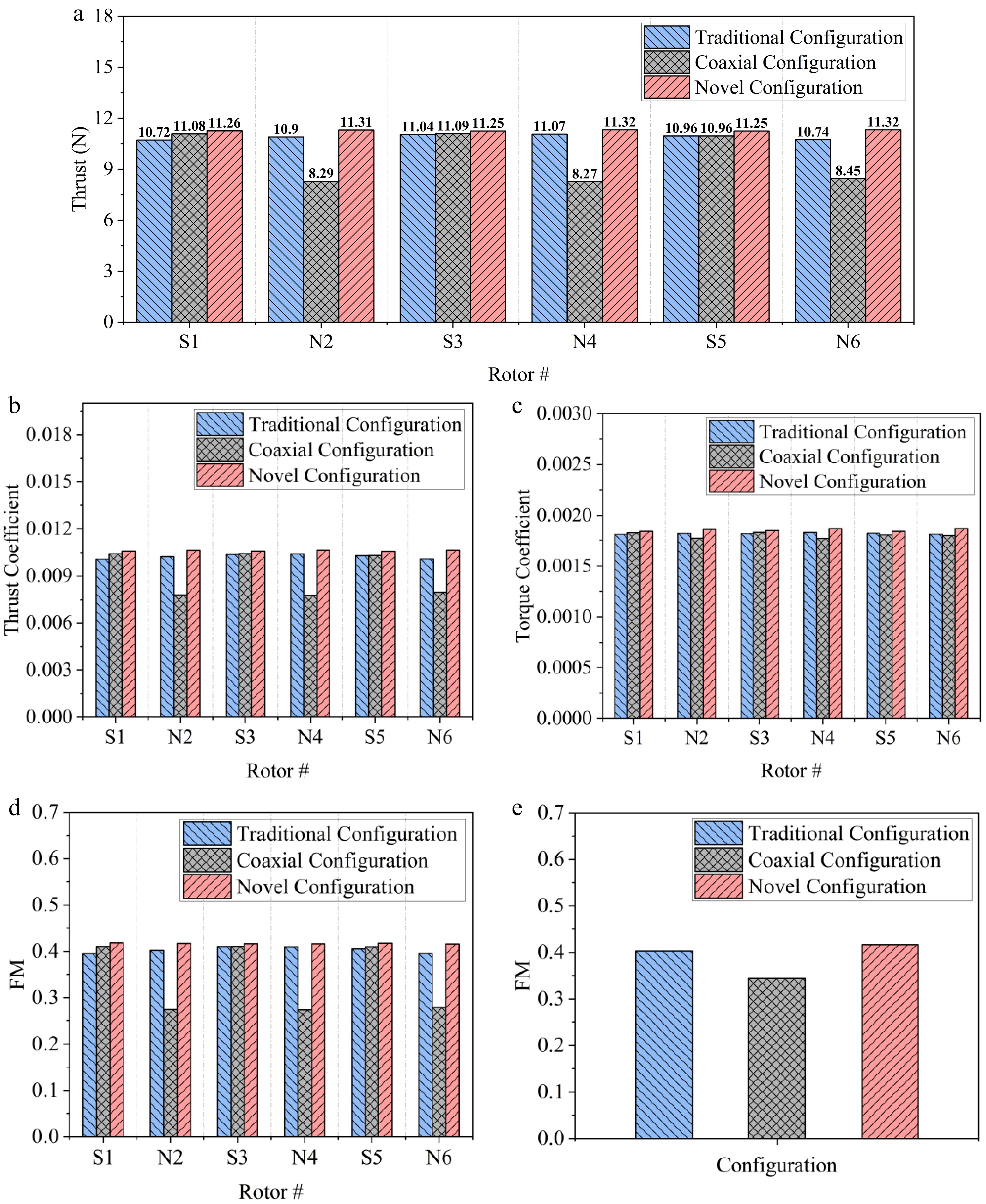
Figure 6.
Aerodynamic performance of three small-sized rotors. (a) Rotor thrust for various configurations. (b)Thrust coefficient. (c) Torque coefficient. (d) FM of each rotor. (e) Average FM of the hexacopter.
To further interpret the performance differences described above, it is necessary to analyze the flow-field characteristics based on the CFD results. Figure 7 illustrates the typical flow structures in hover for the three small-rotor hexacopter configurations: the traditional single-layer layout, the coaxial dual-layer layout, and the novel staggered layout. Distinct differences can be observed among these configurations in terms of vortex structures, wake convergence height, and induced velocity distribution. For the traditional single-layer configuration, independent helical vortex columns form beneath each rotor, with a relatively discrete vorticity distribution. Noticeable lateral interaction occurs between rotor disks, and the local induced velocity exhibits significant fluctuations, leading to poor flow uniformity in the wake region. In the coaxial configuration, the wakes of the upper and lower rotors rapidly merge beneath the rotor disks and form a high-intensity vortex tube, manifested as a vertically elongated region of high Q-criterion values, accompanied by a strong negative z-velocity region. This indicates that the lower rotor operates within a high downwash flow dominated by the upper rotor's wake, resulting in increased inflow angle and reduced effective angle of attack, which in turn intensifies blade–vortex interactions and thrust loss. By contrast, the novel staggered configuration exhibits significant improvement. The upper and lower rotors are arranged in a staggered manner with a certain radial offset, causing their wakes to be spatially displaced rather than directly overlapping. As a result, the wake convergence height is substantially delayed, the downwash flow becomes smoother, and the induced velocity distribution is more uniform, indicating that inter-rotor interference effects are greatly reduced.
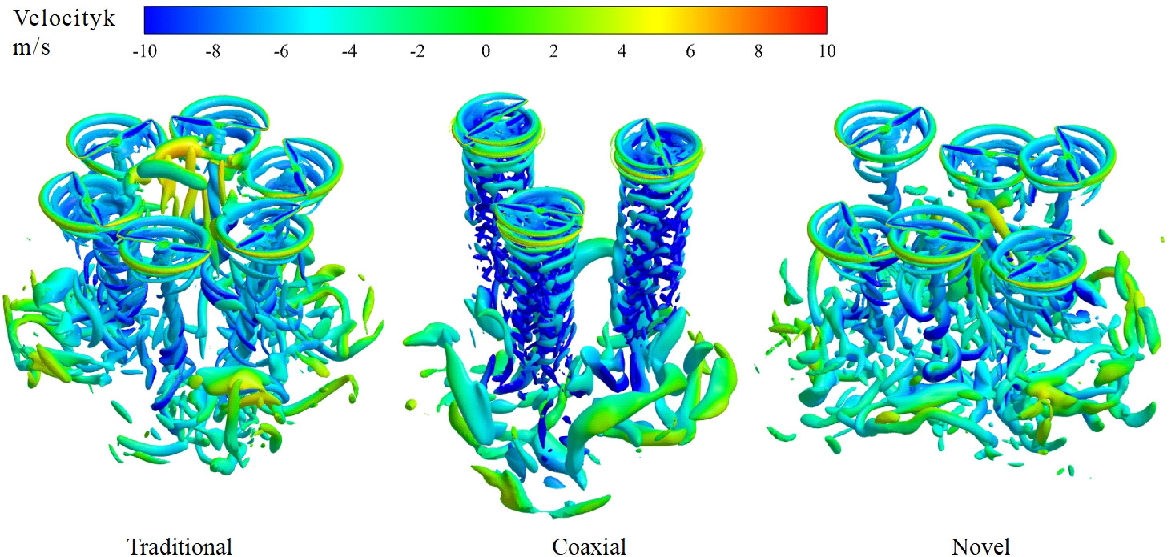
Figure 7.
Isosurface of Q-criterion and z-velocity for small-size rotors.
Figure 8a, b shows the velocity contours and axial velocity distribution along the z-axis in the central region of the hexacopter system, revealing that both the single-layer configuration and the new staggered configuration exhibit an upwash region at the vehicle center, opposite to the direction of the rotor wake. This phenomenon is most pronounced in the traditional single-layer configuration, where the upwash region extends more than two rotor radii above the rotor disk plane. In contrast, the upwash flow in the novel configuration extends above the lower rotor disk, and its velocity magnitude weakens significantly upon reaching the upper rotor disk. Meanwhile, the upwash velocity is notably lower than that of the traditional single-layer hexacopter system. The formation mechanism of this upwash is similar to the fountain flow observed in ground effect: as multiple rotor wakes descend, the central region of the fuselage develops a local low-pressure zone due to wake convergence. Surrounding flow is forced inward and collides beneath the rotor disks; the downward-moving wake interacts with the descending tip vortices, inducing a reverse upwash along the central axis. As shown in Fig. 8c, which presents the axial (z-direction) velocity distribution on the rotor-disk cross section, the upwash appears after the wake convergence and collision region. However, the initial location of wake convergence differs among configurations. As can be seen from Fig. 8b, for the single-layer configuration, upwash begins to form at approximately z/R ≈ 1.3 above the rotor disk. In the new staggered configuration, due to the axial spacing between the upper and lower rotors, the wake convergence point is shifted downward, forming at around z/R ≈ 2.1 relative to the lower rotor disk, thereby weakening both the intensity and spatial extent of the fountain flow. By modifying the wake convergence pattern, the staggered configuration effectively reduces the central fountain upwash, which contributes to improving wake-field uniformity and enhancing the system's hover aerodynamic efficiency.
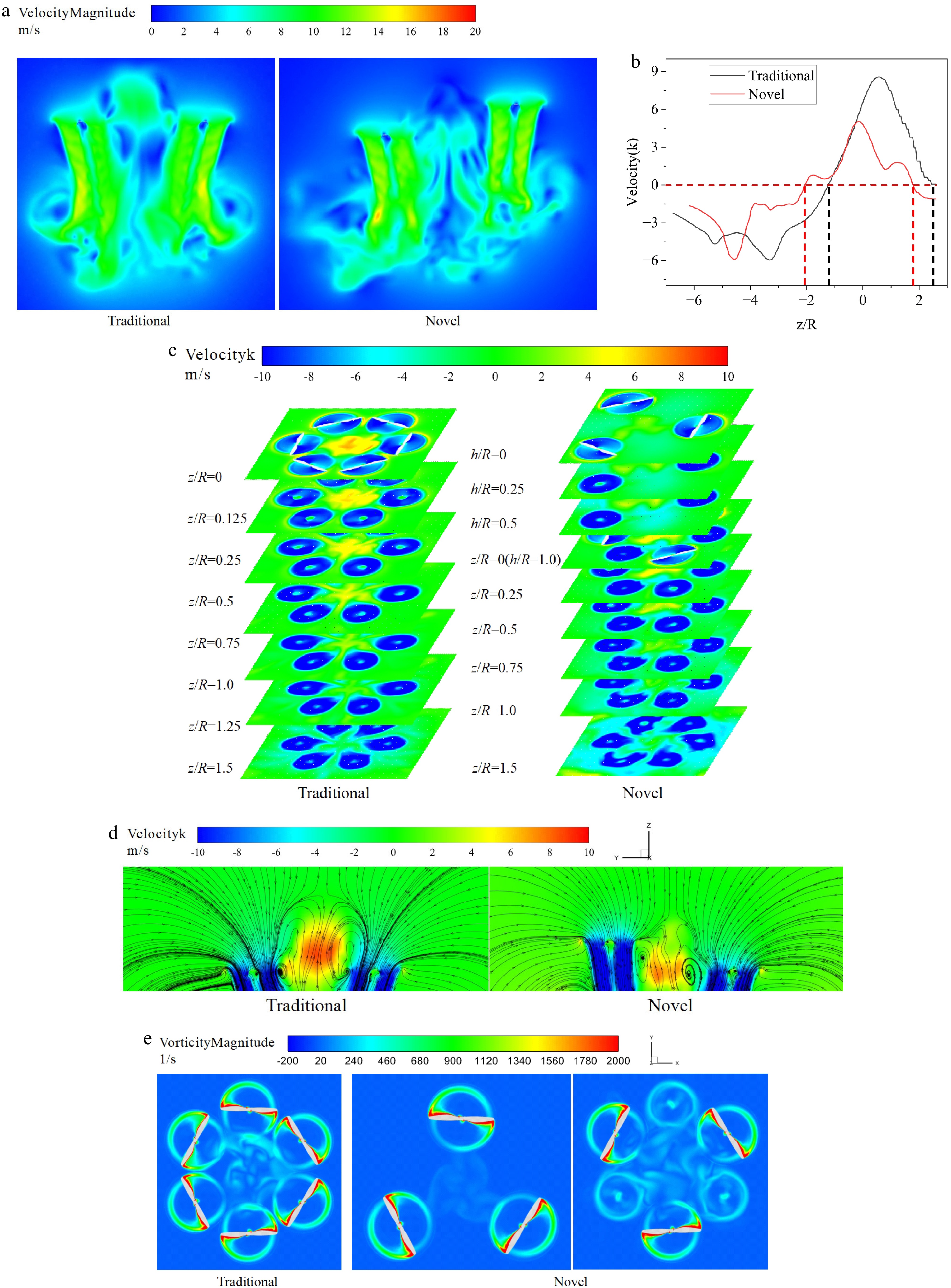
Figure 8.
(a) Downwash velocity distributions. (b) Axial velocity distribution along the z-axis in the central region of the hexacopter system. (c) z-Velocity distributions. (d) z-Velocity-streamline distributions. (e) Vorticity distribution at the rotor disk plane.
Figure 8d shows the distribution of axial velocity (z-direction) and streamlines on the rotor-disk cross section for the single-layer and the new staggered configurations. Here, an inflow angle of
$ \varphi $ $ \varphi $ Figure 8e shows the vorticity distribution on the rotor-disk plane for the traditional single-layer hexacopter and the new dual-layer staggered configuration in hover. As seen in the figure, the traditional configuration produces high-vorticity tip-vortex rings around each rotor, which strongly interact in the central region, leading to noticeable vortex merging and increased flow unsteadiness. In contrast, in the new staggered configuration, the tip-vortex structures of the upper and lower rotors are spatially offset, resulting in a significantly weakened vorticity level in the central area. This indicates that both wake convergence and rotor–rotor interference are effectively suppressed. These results demonstrate that the staggered arrangement improves flow-field uniformity and enhances the system's aerodynamic efficiency by altering the wake topology.
Figure 9 illustrates the periodic variation of rotor thrust with azimuth angle for the traditional single-layer, coaxial dual-layer, and new staggered configurations in hover. The results show that the traditional configuration exhibits pronounced thrust fluctuations, with a maximum amplitude reaching 13.2% of the mean thrust, and noticeable phase differences among rotors, indicating strong wake–wake interactions between rotor disks. In the coaxial configuration, the thrust of the upper and lower rotors shows a clear out-of-phase oscillation, with the lower rotor experiencing the strongest influence from the upper rotor's wake. Its fluctuation amplitude reaches 35.59%, reflecting a further increase in flow unsteadiness. In contrast, the new staggered configuration exhibits much smaller thrust fluctuations, with a maximum amplitude of only 9.3%, demonstrating that the staggered layout effectively weakens blade–vortex interactions and reduces induced-velocity nonuniformity, thereby improving aerodynamic load distribution and enhancing hover stability.
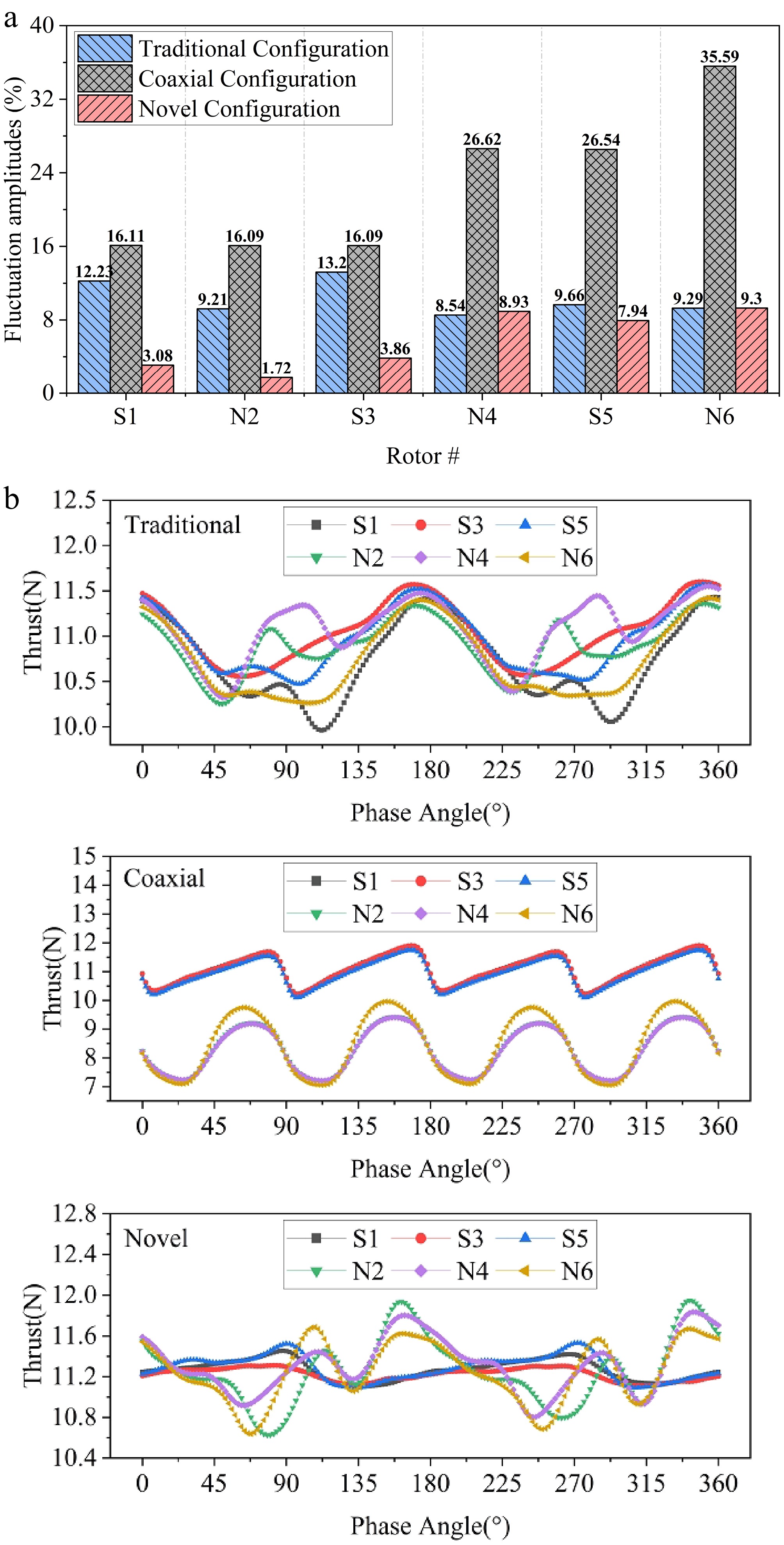
Figure 9.
(a) Ratios of peak-to-trough fluctuation amplitudes of instantaneous thrust to mean thrust. (b) Thrust variation with phase during one revolution.
Performance of different configurations with large-size rotors
-
The new configuration allows the installation of larger rotors than those used in the single-layer layout without increasing the overall size of the UAV, thereby enhancing payload capacity and meeting the requirements of high-load missions in confined environments. To evaluate its hover performance under large-rotor conditions, a comparative analysis was conducted between the new configuration and the coaxial configuration when the rotor radius was increased to the geometric upper limit of 430 mm.
According to the CFD results shown in Fig. 10a, the total thrust of the new configuration is 4.1% higher than that of the coaxial configuration. As shown in Fig. 10a and b, both configurations exhibit the trend that the upper rotor produces more thrust than the lower rotor. However, the upper rotor of the new configuration generates noticeably higher thrust than that of the coaxial configuration, while the lower rotor produces slightly less thrust. Figure 10c shows that the torque differences between the two configurations are relatively small. The new configuration exhibits a more pronounced difference between the upper and lower rotors, whereas the torque of the coaxial rotors is nearly identical. The thrust and torque distribution characteristics of the new configuration are mainly related to the radial distance between rotors (stagger ratio). As the rotor radius increases, the stagger ratio decreases from l/R = 2.5 to l/R = 1.4. According to previous studies[36], the reduction in stagger ratio has a more significant effect on the lower rotors, leading to degraded performance of the lower rotors. Figure 10d presents the FM distribution of each rotor. The results indicate that both configurations maintain the trend of the upper rotor having a higher FM than the lower rotor. However, the FM values of both the upper and lower rotors in the new configuration are higher than those of the corresponding rotors in the coaxial configuration. The system-level FM is shown in Fig. 10e. The new configuration achieves an FM 6.9% higher than that of the coaxial configuration, demonstrating that it can still maintain superior hover efficiency even when equipped with large-diameter rotors.
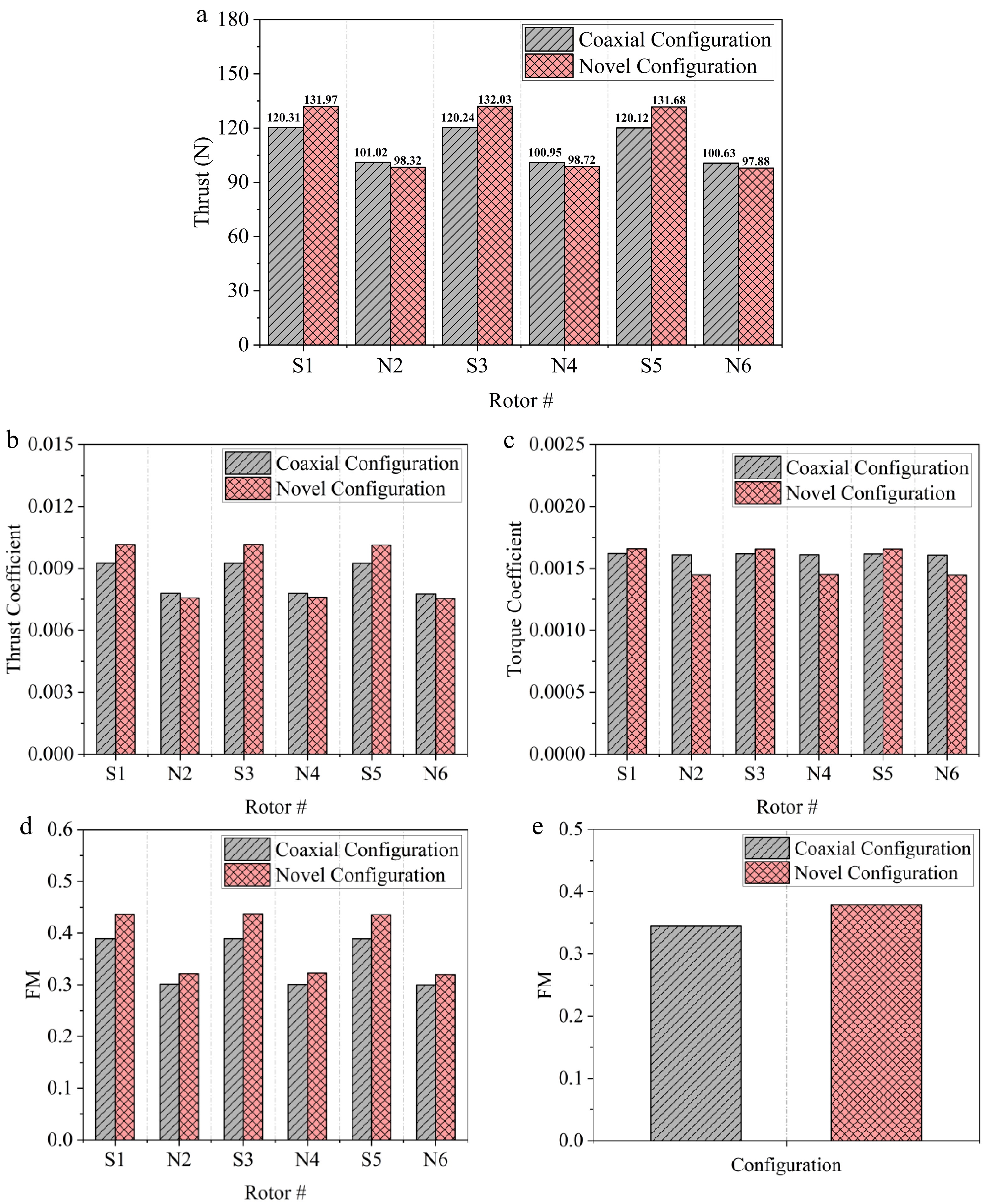
Figure 10.
Aerodynamic performance of three large-sized rotors. (a) Rotor thrust. (b) Thrust coefficient. (c) Torque coefficient. (d) FM of each rotor. (e) Average FM of the hexacopter.
Figure 11 shows the Q-criterion isosurfaces and the axial (z-direction) velocity distribution of the coaxial and new staggered configurations under large-rotor conditions, revealing the differences in wake evolution and induced-flow characteristics during hover. Both configurations generate typical tip-vortex rings and downward-extending helical vortex tubes, but their wake structures differ significantly. For the coaxial configuration, the wakes of the upper and lower rotors strongly overlap along the axial direction, forming a vertically continuous vortex column. The tip vortices of the upper rotor are re-ingested above the lower rotor disk, producing a pronounced high-Q region and a concentrated strong downwash. This indicates substantial blade–vortex interactions between the two rotors. The lower rotor is heavily influenced by the induced velocity field of the upper rotor's wake, resulting in inflow non-uniformity and increased induced power. Meanwhile, the central axis region exhibits complex vortex entanglement and recirculation, enhancing local energy dissipation and further degrading hover efficiency. In contrast, the new staggered configuration introduces spatial offset in both the axial and radial directions, causing the wakes of the upper and lower rotors to spread in a staggered manner. As shown by the Q-criterion iso-surfaces, the wakes exhibit a wave-like vertical distribution, and the vortex structures between rotor disks no longer directly overlap. The concentration of high vorticity in the central region is significantly reduced. The z-velocity distribution further shows that the region of negative velocity is smaller, the downwash intensity is slightly lower than that of the coaxial configuration, and the velocity field is more uniform, with a smoother induced flow. The wake convergence height is markedly delayed, and rotor–rotor interference is effectively mitigated.
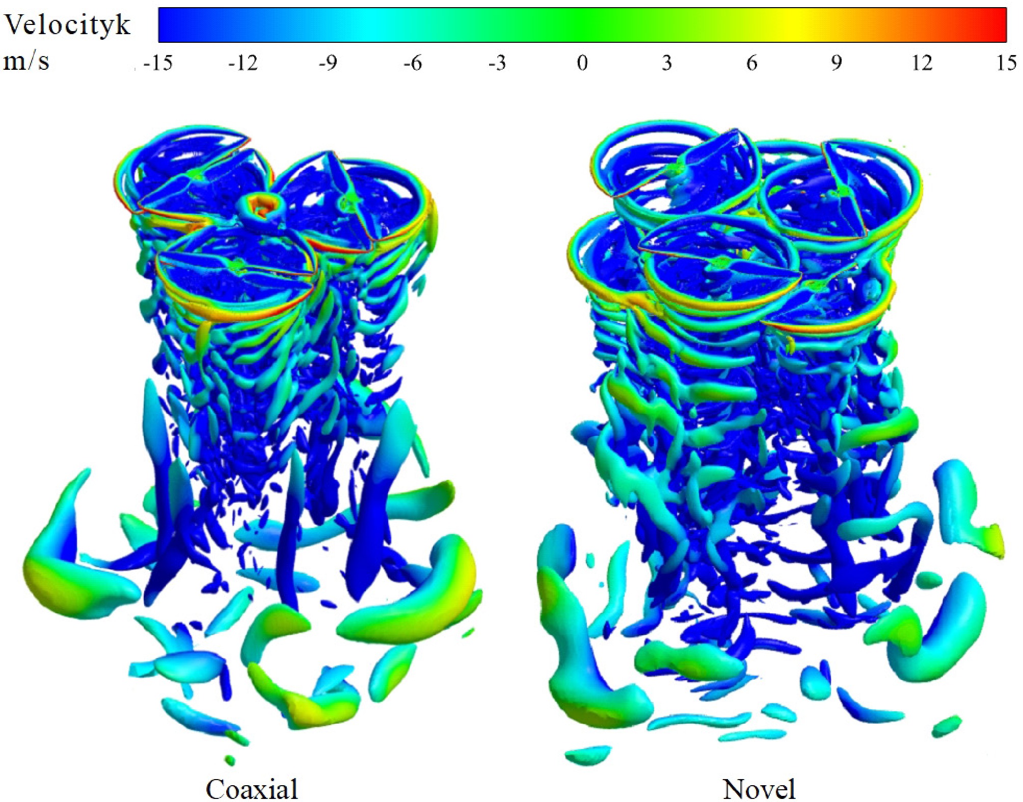
Figure 11.
Isosurface of Q-criterion and z-velocity for large-size rotors.
Compared with the small rotor case, large rotors operate at a higher Reynolds number and generate stronger induced momentum, resulting in more compact wake structures and more concentrated downwash flows. However, the characteristics and distribution differences of the upwash region are more pronounced. In the longitudinal sectional view (Fig. 12a), both configurations exhibit a fountain-type upwash at the vehicle center, opposite to the direction of the main wake. For the coaxial configuration, the upwash region is considerably larger, with its upper boundary extending to the plane of the upper rotor disk, where a distinct high-velocity reverse flow can be observed. This indicates that the wake of the lower rotor converges and collides in the central region, then reflects upward along the axis, forming a typical fountain-flow structure. In contrast, the new staggered configuration shows a much smaller upwash region, extending only slightly above the lower rotor disk and with a lower velocity magnitude compared with the coaxial case. This demonstrates that the staggered layout, by altering the wake convergence path, effectively weakens both the intensity and the spatial extent of the central reverse flow, resulting in a more uniform induced-flow distribution.
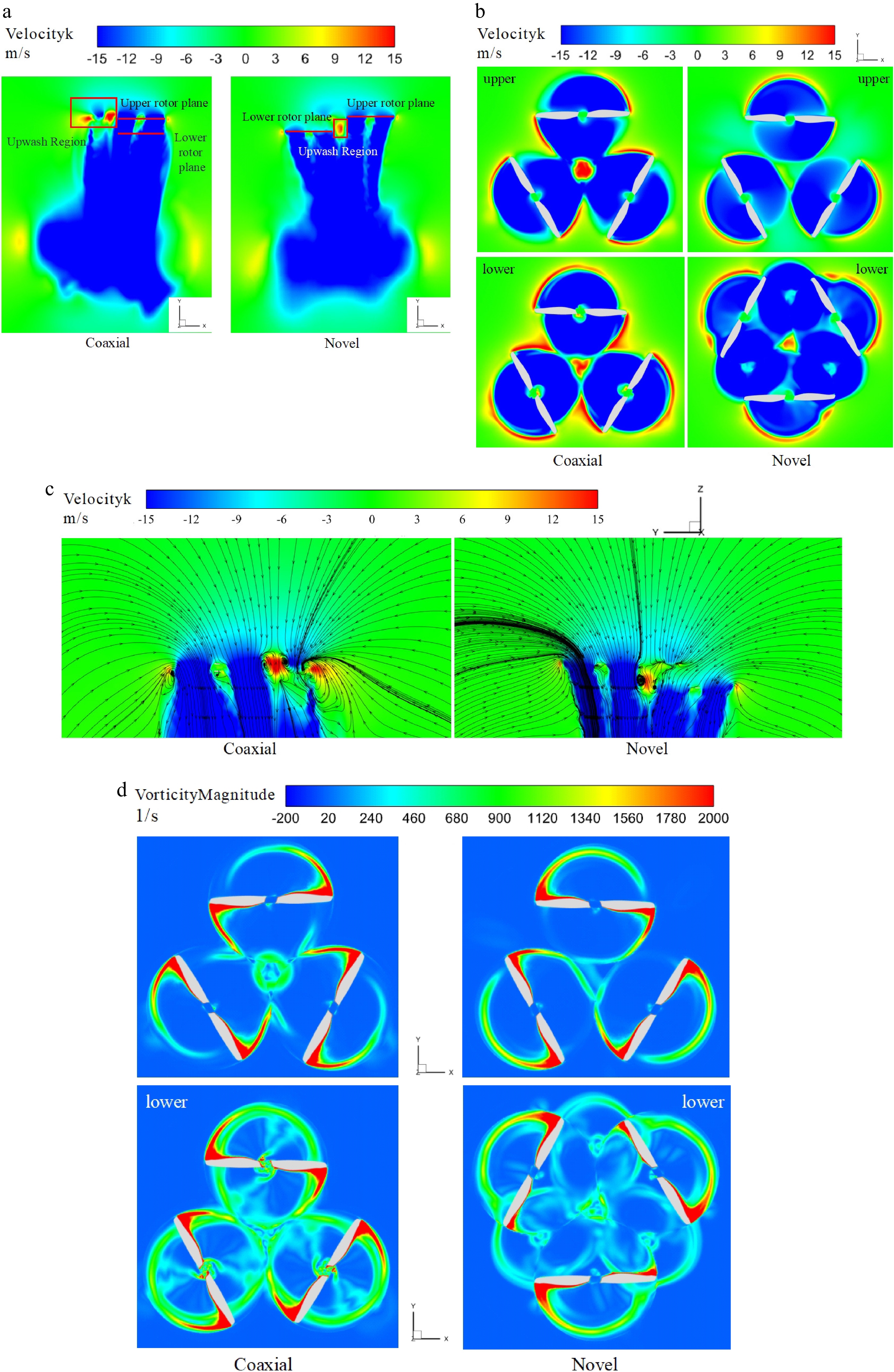
Figure 12.
(a) Downwash velocity distributions; (b) z-velocity at the rotor disk plane; (c) z-velocity-streamline distributions; (d) vorticity distributions at the rotor disk plane.
As can be seen from the rotor-disk plane velocity contours in Fig. 12b, both configurations with large-scale rotors retain the characteristic that the upper rotor produces strong downwash and the lower rotor is significantly affected by interference, but there are notable differences in the flow-field distribution pattern. In the coaxial configuration, the wakes of the upper and lower rotors strongly overlap in the central region, causing the upwash to penetrate directly along the axial direction. In contrast, in the new staggered configuration, the high-velocity region at the center becomes dispersed, reducing the energy concentration of the fountain-type upwash and producing a smoother flow field. Notably, on the lower rotor plane, the staggered configuration exhibits a more symmetric downwash velocity distribution, with a reduced induced-velocity gradient, indicating a more stable inflow across the rotor disk.
Figure 12c presents the z-velocity and streamline distributions. The overall mean inflow angle of the rotor system in the new configuration is larger than that in the coaxial configuration. The upwash vortex below the upper rotor has a more significant influence on the flow direction in the new configuration. The reverse flow induced by this vortex makes the flow direction within the upper rotor disk more radial, resulting in a notably larger mean inflow angle in this region. In contrast, although the coaxial configuration also exhibits a strong upwash, it primarily acts to increase the inflow velocity rather than alter its direction. Combined with the induced suction effect of the lower rotor, this results in a relatively smaller mean inflow angle for the upper rotor in the coaxial layout. Therefore, the effective angle of attack of the upper rotor in the new configuration is larger than that of the coaxial configuration, corresponding to a higher thrust coefficient. Meanwhile, because the drag component also increases, its torque is higher than that of the coaxial configuration rotor.
Figure 13b presents the thrust variation over one revolution for the different configurations equipped with large rotors, and Fig. 13a lists the ratio of peak-to-trough thrust fluctuation to the mean thrust, quantifying the unsteady load characteristics. Overall, both configurations exhibit clear periodic fluctuation patterns, and compared with the small-rotor case, the amplitude and periodicity of the thrust variations become more pronounced. In the new staggered configuration, two dominant thrust cycles appear within one revolution. The lower rotor exhibits a significantly larger fluctuation amplitude than the upper rotor, indicating that it experiences the strongest combined interference from the upper-rotor wake and the tip vortices of the rotors in the same layer within the highly induced flow region. The coaxial configuration also exhibits a double-cycle fluctuation pattern, but the upper rotor shows a far larger fluctuation amplitude than in the staggered configuration. This indicates that, under large-rotor conditions, the upper-rotor flow field is strongly disturbed by the central fountain-type upwash and the reflected wake from the lower rotor.
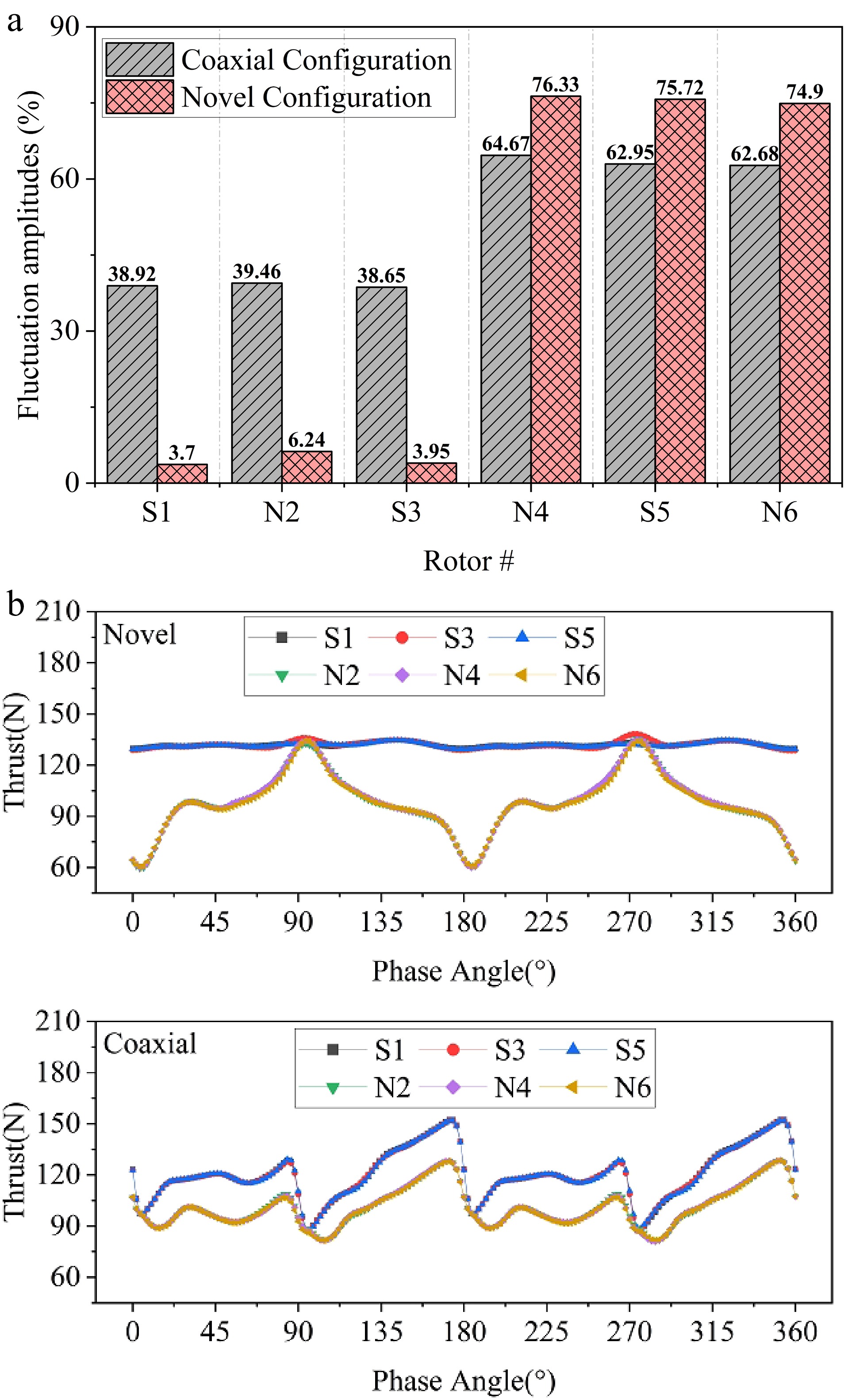
Figure 13.
(a) Ratios of peak-to-trough fluctuation amplitudes of instantaneous thrust to mean thrust; (b) thrust variation with phase during one revolution.
From the quantitative results shown in Fig. 13a, the maximum thrust fluctuation amplitude of the lower rotor in the new configuration reaches 76.33%, significantly higher than the 64.67% observed in the coaxial configuration, whereas the fluctuation amplitude of the upper rotor is only 6.24%, much lower than the 39.46% in the coaxial case. This indicates that the staggered configuration, through spatial offsetting of the rotor layers, effectively reduces the unsteady disturbances acting on the upper rotor, although the lower rotor remains influenced by the combined induced effects of the wake interactions. Overall, the new configuration maintains a more stable aerodynamic load on the upper rotor, while concentrating more of the energy exchange within the lower wake region, thereby improving the uniformity of the induced flow at the system level. It should be noted that the use of large rotors significantly intensifies aerodynamic interactions within the system. Increasing the rotor radius not only reduces the tip-to-tip spacing and strengthens same-layer flow interference, but also makes the central fountain flow more concentrated and enhances wake re-ingestion effects. As a result, both configurations exhibit larger aerodynamic load fluctuations than in the small-rotor case, with substantially increased unsteady loads and reduced hover stability. However, compared with the coaxial layout, the new configuration still demonstrates superior aerodynamic stability and thrust consistency in the upper-rotor region, highlighting its layout advantages and disturbance-mitigation capability in large-scale multirotor systems.
-
To verify the flight feasibility and control stability of the proposed dual-layer hexacopter, prototype flight tests were conducted. The layout control scheme, prototype, and flight test used for the flight experiments are shown in Fig 14. The objective of these tests was to evaluate the flight performance of the proposed configuration under a conventional PID controller. The experiments consisted of two parts: hardware integration and flight validation. The hardware integration included the assembly of the propulsion system, airframe structure, and control and communication modules, ensuring that the prototype possessed independent takeoff and attitude-holding capability. The flight validation phase primarily tested the vehicle's attitude response, thrust allocation, and control stability during hover and small-amplitude maneuvering conditions.
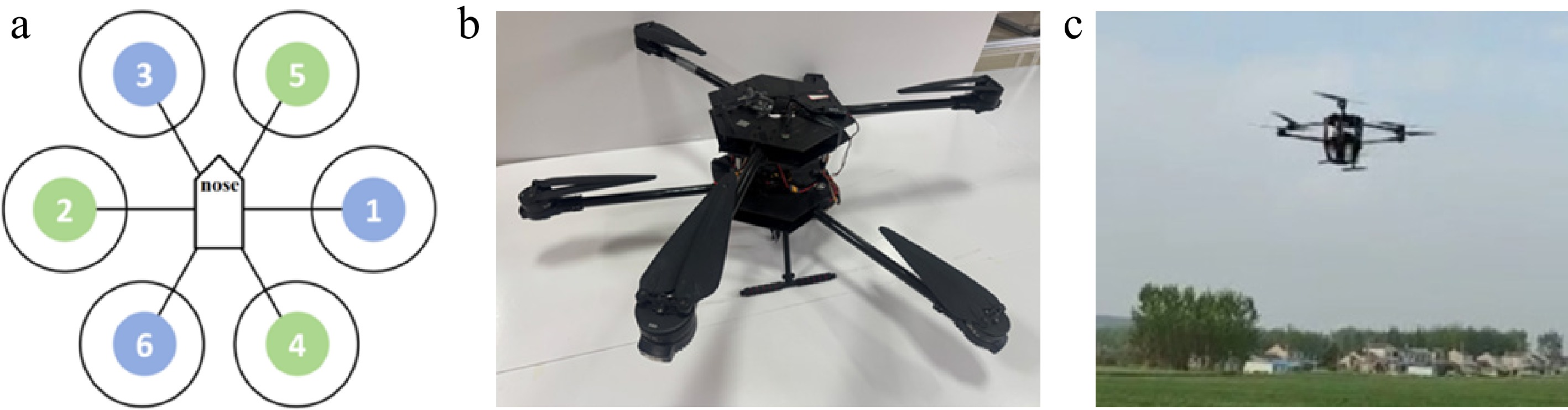
Figure 14.
(a) 'X' layout control scheme; (b) prototype of the novel hexacopter configuration; (c) flight test.
The novel dual-layer staggered hexacopter proposed in this study demonstrates good control compatibility, allowing it to utilize the same control strategy as conventional hexacopter platforms. In terms of control difficulty, the proposed configuration is essentially equivalent to traditional multirotor systems and does not introduce additional control complexity. In this flight test, the prototype took off in an 'X-type' configuration, and the planned flight missions included altitude-hold hover, forward flight, and sideward flight. Figure 15a shows the PWM signals of all motors over time, where motors 2, 4, and 5 belong to the upper layer and motors 1, 3, and 6 belong to the lower layer. The PWM value can be used as an approximate indicator of motor throttle, with a typical range of 1,000–1,900, where larger values correspond to higher motor speed and greater thrust output. As shown in Fig. 15a, the flight sequence contains three phases: (1) 30–50 s: Hover at fixed altitude. All motor PWM signals remain stable, indicating good thrust balance. (2) 50–90 s: Small-amplitude forward and lateral maneuvers. Several motor PWM signals exhibit phase-dependent fluctuations, corresponding to the real-time attitude corrections performed by the control system. (3) 90–100 s: Landing phase. The PWM signals decrease overall and gradually return to the initial values. Figure 15b–d presents the time histories of roll, pitch, and yaw angles during the flight. The results show only small attitude fluctuations, and the system maintains stable responses throughout the test. These findings demonstrate that the proposed configuration achieves good hover control accuracy and flight stability under the 'X-type' control scheme.
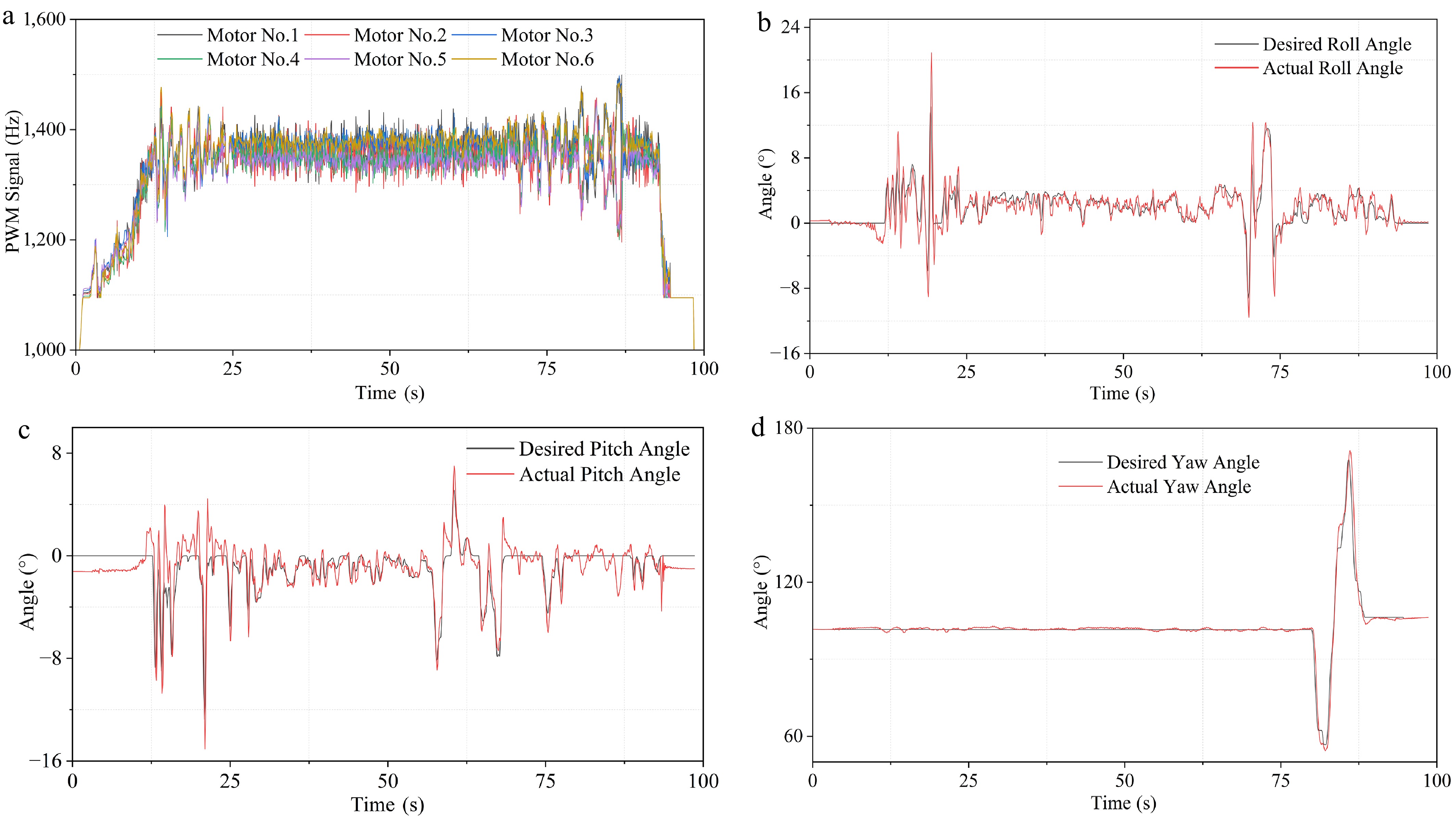
Figure 15.
(a) PWM signals of six motors over time; (b) time history of roll angle; (c) time history of pitch angle; (d) time history of yaw angle.
-
In this study, a novel double-layer staggered hexacopter configuration is proposed. Through CFD numerical simulations and flight tests, comparisons with the conventional single-layer and coaxial configurations yield the following main conclusions:
(1) Significant improvement in aerodynamic performance: With the same fuselage size, the new configuration can accommodate larger rotors, thereby increasing total thrust and hover efficiency. For small rotors (R = 230 mm), total thrust is increased by 16.4% and the overall figure of merit (FM) by 21.2% compared with the coaxial configuration. For large rotors (R = 430 mm), total thrust is increased by 4.1% and the overall FM by 6.9%, demonstrating favorable scalability.
(2) Remarkably reduced unsteady load fluctuations: The spatial staggered arrangement of rotors results in more stable thrust variations. For small rotors, the maximum thrust fluctuation of the new configuration is only 9.3%, much lower than 35.6% for the coaxial configuration. For large rotors, the fluctuation of the upper rotor is merely 6.24% (39.46% for the coaxial configuration). The lower rotor experiences a fluctuation of approximately 76% due to the combined effects of tip vortices and in-plane interference, yet the entire system maintains high stability.
(3) Flow-field mechanisms reveal inherent advantages: The conventional coaxial configuration features a vertical through-type wake structure with strong central fountain flow. By introducing axial and radial staggering, the new configuration enables a 'staggered-layer, out-of-phase' wake evolution, which delays the convergence height, weakens the central upwash region, produces a more uniform induced velocity distribution, and reduces wake energy dissipation as well as rotor–rotor interference.
(4) Flight tests verify feasibility: Tests based on the 'X'-type control scheme and a conventional PID controller demonstrate that the prototype can achieve stable hover and mild forward/sideways flight. Reasonable PWM distribution among motors and small attitude angle fluctuations verify the effective compatibility between the new configuration and existing control systems.
This research was funded by the National Natural Science Foundation of China (Nos 52202443, 52572409, 52275114), the Aeronautical Science Foundation of China (No. 20232010052002), and the Fundamental Research Funds for the Central Universities, (No. NT2025001).
-
During the preparation of this work, the authors used ChatGPT (Nov. 2025) for language refinement. The authors reviewed and edited all content produced with the assistance of this tool, verified its accuracy, and take full responsibility for the integrity and originality of the final manuscript. This work represents the authors' own intellectual contribution, and no AI tool is credited as an author.
-
The authors confirm contribution to the paper as follows: study conception and design: Nie H, Wei X; data collection: Chen H, Zhu H; analysis and interpretation of results: Du Y, Zhu H; draft manuscript preparation: Du Y, Zhu H. All authors reviewed the results and approved the final version of the manuscript.
-
The data that support the findings of this study are available from the corresponding author upon reasonable request.
-
The authors declare that they have no financial or personal relationships with other people or organizations that could inappropriately influence our work, and no professional or personal interest of any kind related to any product, service, or company.
- This article is an open access article distributed under Creative Commons Attribution License (CC BY 4.0), visit https://creativecommons.org/licenses/by/4.0/.
-
About this article
Cite this article
Zhu H, Du Y, Nie H, Chen H, Wei X. 2026. Aerodynamic characteristics comparison and assessment of a novel staggered hexacopter. International Journal of Micro Air Vehicles 18: e007 doi: 10.48130/mav-0026-0008 

Aerodynamic characteristics comparison and assessment of a novel staggered hexacopter
- Received: 18 December 2025
- Revised: 09 April 2026
- Accepted: 15 June 2026
- Published online: 12 August 2026
Abstract: Aerodynamic interference between multiple rotors is a key factor limiting the performance of distributed propulsion aircraft. To address the dilemmas that the conventional single-layer hexacopter configuration is constrained by fuselage space and thus difficult to accommodate large-scale rotors, and that coaxial configurations suffer from severe aerodynamic interference between upper and lower rotors, this study proposes and systematically evaluates an innovative dual-layer radially staggered hexacopter configuration. By axially dividing rotors into two layers and staggering them in the radial direction, the proposed design breaks through the limitations of conventional configurations while maintaining fixed fuselage and arm dimensions. A comparative framework is established covering the conventional single-layer, coaxial, and the novel staggered configurations. High-fidelity CFD numerical simulations are conducted to systematically compare and analyze the hover performance, wake evolution, flow-field interference mechanisms, and unsteady load characteristics for two rotor scales: small (R = 230 mm) and large (R = 430 mm). Prototype flight tests are further carried out to verify the flight feasibility and control compatibility of the proposed configuration. This study confirms that the proposed configuration can adapt to larger-radius rotors without increasing the overall aircraft size, and improves hover efficiency and flight stability. It provides an efficient and feasible aerodynamic layout for the design of multi-rotor unmanned aerial vehicles intended for confined spaces and high-payload missions.
-
Key words:
- Hexacopter /
- Aerodynamics /
- Configuration /
- CFD /
- Flight tests