


-
Orchard growers are increasingly adopting air blast sprayers due to their significant advantages over traditional spraying methods. These sprayers offer improved spray performance, cost efficiency, uniform distribution, and decreased labor requirements[1−3]. During the flowering season, rainfall and overcast conditions create a conducive environment for the proliferation of diseases and insect pests. These aggressive pests and diseases pose a considerable threat, potentially resulting in the complete loss of the crop[4−7]. Pradeep et al.[8] highlighted that when mango panicles are affected by pests and diseases, the yield of mangoes may decline by 50%−80%. Consequently, it underscores the importance of spraying to mitigate damage from insects and diseases, thereby controlling their detrimental impact on crop yields. Multiple experiments conducted across different crops using modern techniques have provided evidence that the discharge of chemical substances leads to environmental pollution. Van den Berg et al.[9] illustrated that between 20% to 30% of the material applied is lost to the air, comprising up to 50% of the total applied material. The extent of atmospheric loss, as indicated by Cross et al.[10], depends on various factors, such as the chemical properties of the applied material, atmospheric conditions, and the spraying technologies employed. A variety of technologies[11−14] have been developed for controlling DC motors. Mondal et al.[15] introduced a microcontroller-based embedded system for DC motor control, employing a closed-loop approach. Their system established a continuous closed-loop circuit by harnessing back electromotive force (EMF) generated through the tachogenerator. Gohiya et al.[16] demonstrated a DC motor driving system using an embedded system for a mobile robot. However, a significant limitation of this system is the relatively low processing speed of the processor. The existing air blast sprayer setup necessitates dual operators: one handling the tractor and another stationed at the rear of the sprayer. The second operator is responsible for adjusting the position and direction of the delivery pipe while in operation. However, this arrangement exposes the operator to significant vibration, jerking, and potential pesticide exposure from the polluted air generated during spraying[17,18]. Operator exposure within the pesticide spraying area can have a significant impact on health, as highlighted by Wong et al.[19]. Additionally, workplace vibrations can adversely affect the human body, leading to health issues such as muscle strain, back pain, and spine degeneration[20−22]. The current air blast sprayer presents several challenges, including operator-experienced vibrations and serious hazards for the sprayer operator. Therefore, there is a necessity for modification in the existing system wherein the tractor operator can also manage the sprayer. Eliminating the need for a second operator in the air blast sprayer has driven the design and development of a microcontroller-based automation system to control the spray delivery pipe using a DC motor. The primary goal of this research paper is to devise a mechanism and a microcontroller-based embedded system to rotate the delivery pipe of the air blast sprayer, enabling precise spraying on the target plant.
-
The spray delivery pipe, positioned behind the tractor driver in the air blast sprayer, is currently manually controlled by another operator using an iron wheel. Hence, there is a need for an electronic method to automatically manage and regulate the spray delivery pipe for chemical application. This research aims to design and develop a microcontroller-based embedded system for controlling the spray delivery pipe of a tractor-operated air blast sprayer. A laboratory setup was constructed to assess the performance of the developed embedded system. The setup comprises a spray delivery pipe actuator, a signal generator for determining the required position of the spray delivery pipe, a mechanical position indicator for the spray delivery pipe, and the microcontroller-based embedded system.
Spray delivery pipe controller
-
The spray delivery pipe actuator consists of several components, including a DC motor, position sensor, idle gear, ring and pinion gear, brass pulley, and C clamp. The pipe actuator system was segmented into various units as outlined below.
Upper unit
-
The upper unit consists of a circular plate with an outer diameter of 254 mm and an inner diameter of 183 mm. A ring gear with 80 teeth and a module of 2.5 is securely attached to its upper surface. Additionally, a 238 mm diameter circular flat piece is concentrically welded onto the lower surface, as illustrated in Fig. 1a & b. In the lower unit, the pinion gear meshes with the ring gear (80 teeth, 2.5 module) to rotate the upper unit. The spray delivery pipe is affixed to the ring gear, ensuring that they are coaxial with each other. This setup allows the spray delivery pipe end to rotate within a range of ± 180° from the main position.
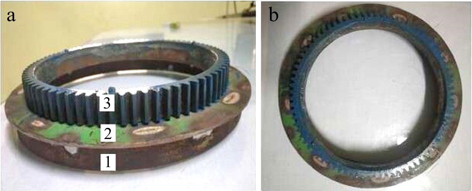
Figure 1.
(a) Front view of upper unit: 1. circular flat; 2. circular plate; 3. ring gear. (b) Top view of the upper unit.
Lower unit
-
A round plate, with an external diameter of 406 mm and an internal diameter of 183 mm, had three brass pulleys situated at a distance of 119 mm from the center, evenly spaced at intervals of 120 degrees. These pulleys were set up to create rotational movement in the upper unit. The motor, a position sensor (R2), and a pinion gear featuring 21 teeth with a 2.5 module dimension were interconnected via a shared shaft. This shaft was upheld by C clamps to ensure stability and accurate alignment. The rotation of the upper unit was facilitated by engaging a pinion gear with a ring gear boasting 80 teeth and adhering to a 2.5 module specification. Additionally, two idler gears were utilized to support the upper unit. Figures 2 & 3 illustrated the schematic and developed lower unit, respectively.
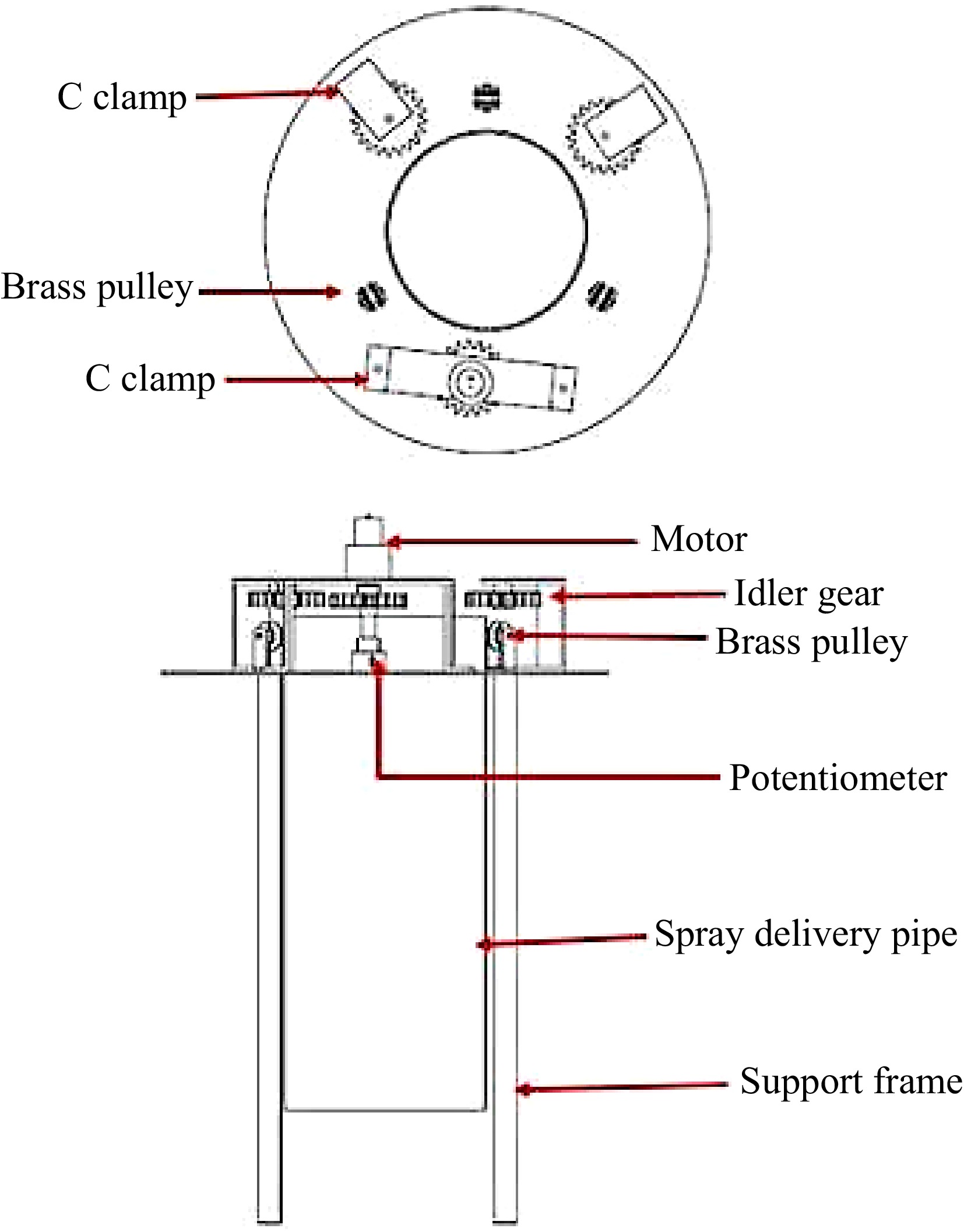
Figure 2.
Sketch of developed lower unit.
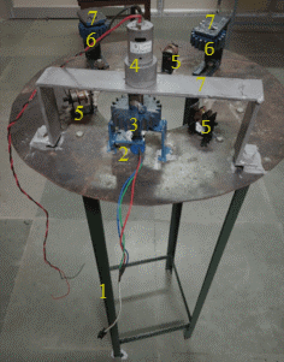
Figure 3.
Schematic view of lower unit: 1. four leg stand, 2. position sensor, 3. pinion gear, 4. motor, 5. brass pulley, 6. idler gear, 7. C clamp.
The operation of the spray delivery pipe actuator relies on comparing the current position, as indicated by the mechanical position indicator, with the desired position from the signal generator. When the signal difference exceeds 27.77 mV, indicating a deviation greater than 2 degrees between the set and current positions, the motor rotates clockwise. Conversely, if the signal difference drops below 0 mV, indicating a deviation of less than 0 degrees, the motor rotates counterclockwise. If the signal difference remains within the range of 0 to 27.77 mV, corresponding to a deviation between 0 to 2 degrees, the motor remains stationary without any rotation. The rotation of the spray delivery pipe is achieved through the operation of an electric motor that drives a pinion gear, meshing with a ring gear attached to the pipe itself. This interaction between the ring and pinion gears enables the rotation of the pipe around its axis when the motor is activated. The electric motor receives power from an embedded system, and its rotational direction is controlled by the polarity of the power supplied by this embedded system.
The embedded system collects input signals from two distinct sources: firstly, from the signal generator, which indicates the desired position of the spray delivery pipe; and secondly, from the mechanical position indicator, which relays feedback signals from the controller regarding the current position of the pipe. A microcontroller, acts as a comparator, within the embedded system analyses and compares these input signals. Based on this comparison, the output of the comparator can be either negative or positive. A negative signal instructs the motor to rotate the pipe anticlockwise, while a positive signal prompts clockwise rotation through the interlocking mechanism of the ring and pinion gears. With this setup, the need for a secondary operator to manually adjust the spray delivery pipe is eliminated. Instead, the system operates autonomously, controlling the positioning of the pipe based on the signals it receives and processes within the embedded system. This automation streamlines the process, enhancing efficiency and reducing the potential for human error.
Signal generator for the required position of the spray delivery pipe
-
The signal generator consists of several components: a lever, a gear assembly comprised of both driven and driving gears, and a position sensor (R1). The position sensor (R1) is connected to the lever through a gear assembly, which incorporates an 8.54 gear reduction ratio. The lever is utilized to adjust the desired position of the spray delivery pipe. These components are installed on a rectangular plate, as depicted in Fig. 4.
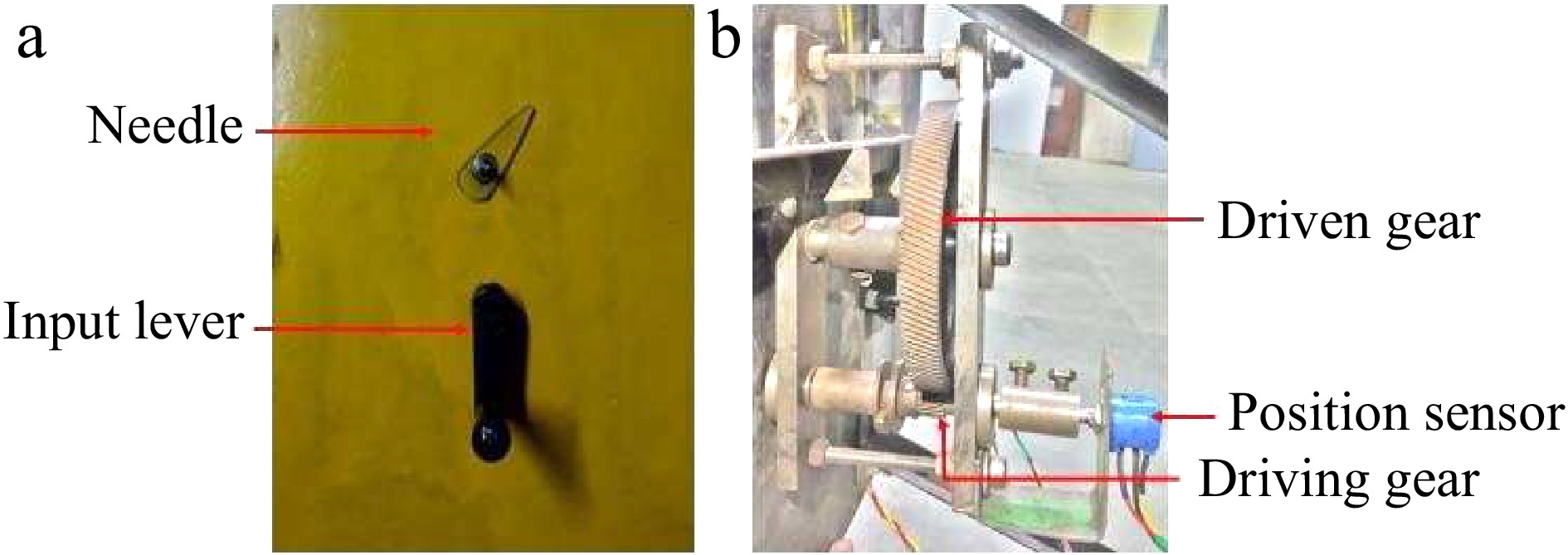
Figure 4.
Photograph of positioning and indicating unit.
The driving gear is positioned on the shaft of the position sensor and remains constantly engaged with the driven gear, forming the gear assembly. This gear assembly is situated at the lower side of the rectangular frame for optimal placement and functionality. The lower end of the driving gear shaft was linked to the position sensor (R1), while the upper end of the shaft was secured with an input lever. Additionally, a needle was attached to the upper end of the driven gear shaft, serving to mechanically indicate the set position of the spray delivery pipe. During the operation of the sprayer, if a new target area needs spraying, the operator adjusts the lever to set a new position. Rotating the lever creates a signal indicating the new position of the spray delivery pipe. The current position of the spray delivery pipe is determined by the spray delivery pipe controller. Both the signal representing the set position and the signal indicating the current location of the spray delivery pipe are input to the microcontroller (comparator). The microcontroller processes these signals and sends them as output to the motor driver. Based on the received signal from the microcontroller, the motor determines the angle and direction of rotation for the spray delivery pipe. The developed signal generator unit for spray delivery is illustrated in Fig. 4.
Mechanical position indicator of spray delivery pipe
-
A needle (indicator) and dial have been used to indicate the set position of the spray delivery pipe, depicted in Fig. 5. The indicator was connected to the driven gear shaft, as mentioned in the generator unit. The set (required) position of the delivery pipe depends on the spraying target area, which was decided by the tractor operator. When the tractor operator fixes the required position of the spray delivery pipe by adjusting the input lever, that position of the spray delivery pipe is shown by an indicator in angle form. The flow chart of the position indicator of the spray delivery pipe is shown in Fig. 5.
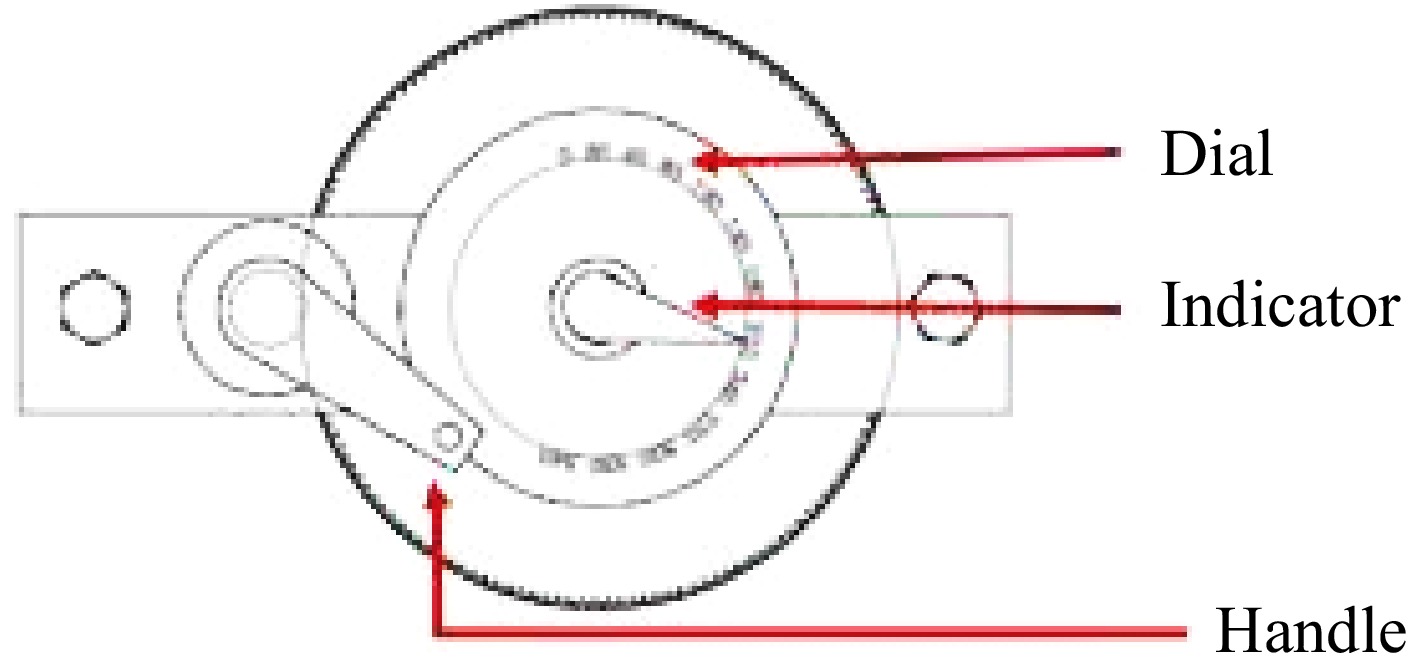
Figure 5.
Position indicator of spray delivery pipe.
Microcontroller-based embedded system
-
The microcontroller-based embedded system (depicted in Supplementary Fig. S1) has been designed to automatically control the rotation of the spray delivery pipe of the air blast sprayer based on signals received from the microcontroller. This system consists of several components, including a microcontroller (Arduino Uno, with 2KB SRAM, Smart Projects, Italy), a DC motor (12 V, 7 kg-cm torque, India), a motor driver (L298N, 5-35V, India), a 12 V DC battery, a position sensor (Potentiometer, 10 K, rotary type, Pot-Tech Electronic, Bombay, India), and an LCD. The developed embedded system incorporates two potentiometers, both of 10 K resistance and featuring 10 turns. The first potentiometer (R1) is positioned for use by the tractor operator, while the second one (R2) is connected to the motor via a shaft for control purposes. The LCD is utilized to display both the set (required) and current positions of the spray delivery pipe. An Arduino code is uploaded to the Arduino Uno via a USB cable to control the rotation of the spray delivery pipe by operating the DC motor. The signal generator lever (shown in Fig. 4) enables the operator to adjust the position of the spray delivery pipe. The signal generated by the lever is transmitted to the DC motor through the microcontroller. Depending on the signal received from the microcontroller, the motor is directed to rotate either clockwise or anticlockwise. The developed embedded system is illustrated in Fig. 5.
-
The developed embedded system for controlling the spray delivery pipe of an air blast sprayer underwent testing at the Farm Machinery Laboratory, Agricultural and Food Engineering Department, Indian Institute of Technology (IIT), Kharagpur, India. Potentiometer R1 is utilized to generate a signal representing the desired position of the spray pipe, with a lever attached to the shaft of the potentiometer to facilitate adjustment. The tractor driver manipulates the lever to rotate the potentiometer shaft, thereby producing a signal that is directed to the microcontroller (comparator) for processing. Another potentiometer, R2 (feedback sensor), is directly installed on the motor shaft to produce a signal representing the current position of the spray pipe, which is also sent to the microcontroller. The comparator evaluates the two signals and generates an output signal proportional to the difference between them. This output signal from the microcontroller is then transmitted to the motor driving unit. Depending on the polarity of the signal, the motor rotates either clockwise or anticlockwise. The potentiometer signals are continuously provided to the comparator, which consistently generates an output signal accordingly. When the comparator's output signal reaches zero, the motor shaft ceases its rotation, aligning the spray pipe movement with the rotation of the motor shaft. Gears serve as a mechanical transmission for this function. Both mechanical and electronic displays indicate the magnitude of the potentiometer-generated signals. The driver sets the required position based on the targeted canopy. The schematic and developed automatic spray delivery pipe control system are shown in Figs 6 & 7, respectively, while the flow chart of the developed spray delivery pipe control system is depicted in Fig. 8.
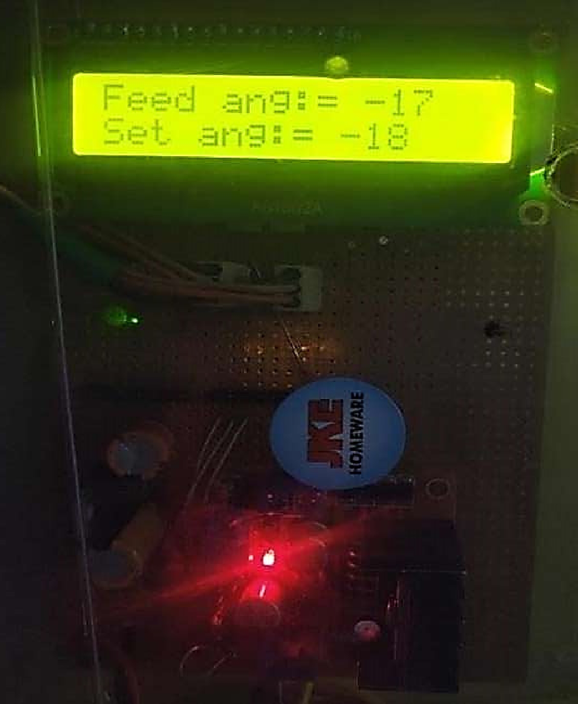
Figure 6.
Developed microcontroller-based embedded system.
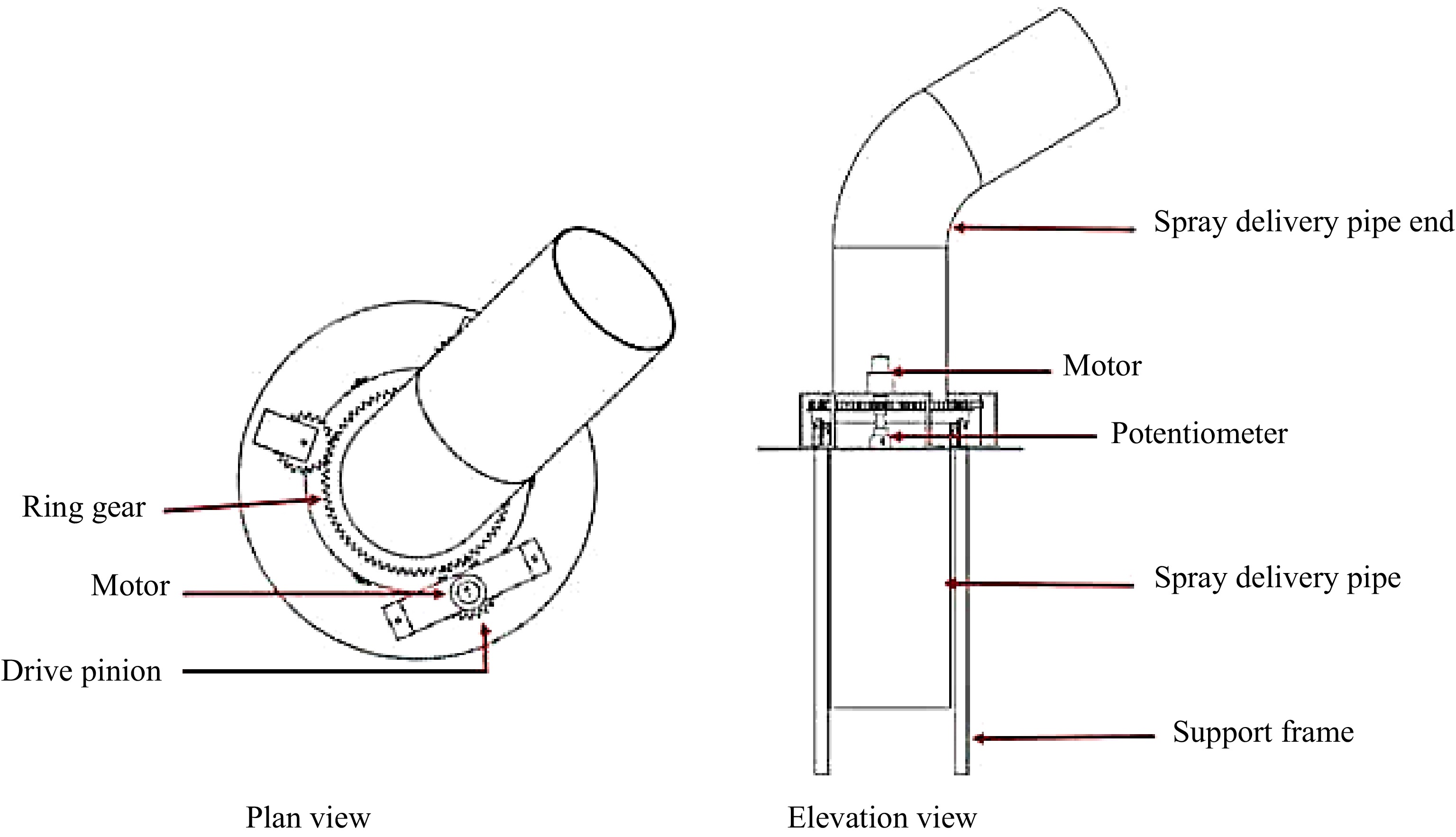
Figure 7.
Sketch of automatic control unit for spray delivery pipe.
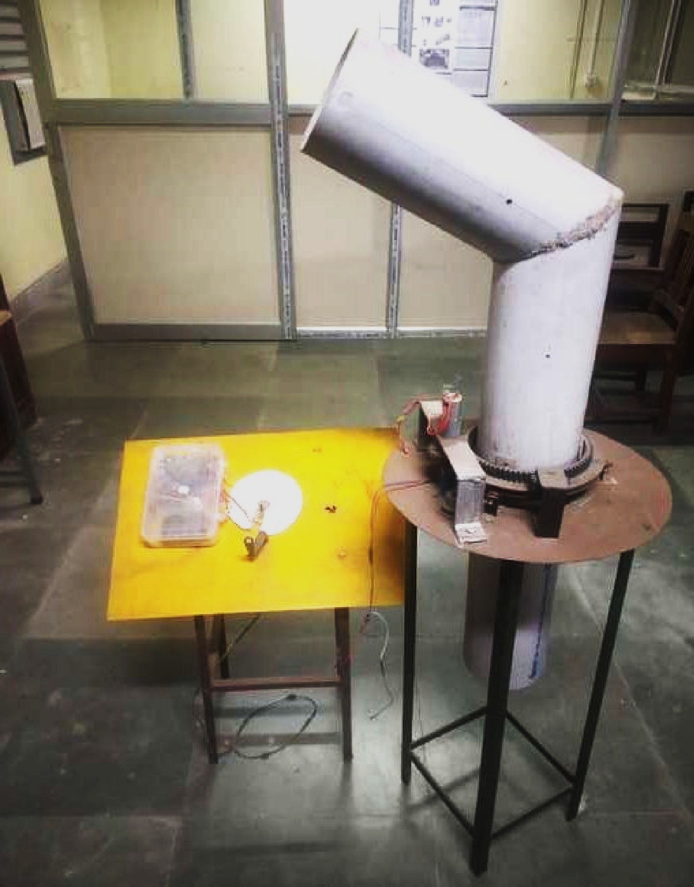
Figure 8.
Developed laboratory setup for the air blast sprayer.
-
The study involved assessing the time variation between the full rotation of the spray delivery pipe as set by the operator and the time required by the developed embedded system to complete the same rotation. This comparison was conducted by rotating the lever either clockwise or anticlockwise. Figure 9 illustrates the cumulative duration required for the spray delivery pipe to complete a rotation spanning from −180 to 180 degrees. The embedded system exhibits a delay of 2.024 s. In the counterclockwise direction, the embedded system consumes 36.48 s for a complete rotation. Conversely, a 0.45% variation is observed in the clockwise direction. Rotating the input lever takes 4.82 s in the counterclockwise direction and 4.74 s in the clockwise direction. The observed variation in handle rotation time is 1.65%.
Figure 9.
Schematic layout of the automatic spray pipe positioning and indicating system.
Step input positioning of spray delivery pipe
-
Figure 10 illustrates the step input positioning of the spray delivery pipe, showcasing the time taken for the pipe to complete its rotation by the set position determined by the lever. The assessment involved adjusting the position in increments of 30 degrees within a range of −180 to +180 degrees using the lever. It was observed that each step input took approximately 2 s to execute. Upon initiating the lever's rotation, there was a 1-s delay before the spray delivery pipe began its rotation. On average, the pipe took 2.31 s to complete a 30-degree rotation once in motion. The delay or response time between the set position of the lever and the embedded system's reaction time was measured at 1.33 s. Figure 11 visually depicts a direct relationship: as the set angle of the spray delivery pipe increased through lever adjustment, the position of the spray delivery pipe was correspondingly adjusted.
Figure 10.
Real-time position control of spray delivery pipe.
Figure 11.
Real-time response for every 30° rotation of spray delivery pipe.
Comparison between the set position and current position of the delivery spray pipe
-
The comparison between the set position and the current position of the spray delivery pipe is shown in Fig. 12. It was noted that the current position of the spray delivery pipe closely aligns with the set position, fluctuating within the range of 0° to 2°. This suggests that the developed system is highly accurate. Moreover, it was observed that the system operates with remarkable precision, especially beyond 20°.
Figure 12.
Comparison between set position and current position of delivery spray pipe.
-
A microcontroller-based embedded system was designed to manage the spray delivery pipe of a tractor-operated air blast sprayer. This system included components such as a position sensor, DC motor, motor driver, microcontroller, 12V DC battery, and LCD. The performance of this system was assessed in laboratory conditions, revealing that it took 36.48 s to complete one rotation of the spray delivery pipe, with a variation of 0.45% in the clockwise direction. Additionally, the system delay was measured at 2.024 s, and the angle error ranged from 0 to 2 degrees. Overall, the developed microcontroller-based embedded system effectively controlled the spray delivery pipe, and the absence of a second operator did not significantly impact its performance. The laboratory setup designed for this purpose enhances the spraying system of the air blast sprayer, offering efficient control of the spray delivery pipe. The limitation of this developed system is that it takes more time to control the spray delivery pipe of the air blast sprayer; in the future, a developed embedded system can be tested under field conditions.
-
The authors confirm contribution to the paper as follows: study conceptualization, formal analysis, validation, visualization: Chouriya A, Thomas EV; data curation, methodology, investigation, software, writing-original draft: Chouriya A; writing-review and editing, resources: Singh R, Thomas EV; supervision, project administration: Thomas EV. All authors reviewed the results and approved the final version of the manuscript.
-
The datasets generated during and/or analyzed during the current study are available from the corresponding author on reasonable request.
-
Research facilities of the Indian Institute of Technology Kharagpur were thankfully used to conduct this research work.
-
The authors declare that they have no conflict of interest.
- Supplementary Fig. S1 Electronic circuit of developed embedded system.
- Copyright: © 2025 by the author(s). Published by Maximum Academic Press, Fayetteville, GA. This article is an open access article distributed under Creative Commons Attribution License (CC BY 4.0), visit https://creativecommons.org/licenses/by/4.0/.
-
About this article
Cite this article
Chouriya A, Singh R, Thomas EV. 2025. Development of a microcontroller-based embedded system for position control of spray delivery pipe of tractor-operated air ballast sprayer. Technology in Agronomy 5: e009 doi: 10.48130/tia-0024-0027 

Development of a microcontroller-based embedded system for position control of spray delivery pipe of tractor-operated air ballast sprayer
- Received: 08 July 2024
- Revised: 06 August 2024
- Accepted: 27 August 2024
- Published online: 04 June 2025
Abstract: A traditional air blast sprayer typically relies on an additional operator to manage the positioning of the spray delivery pipe. To eliminate the need for a second operator, a microcontroller-based embedded system was developed and tested under laboratory conditions using a specialized setup. This system consisted of several components: a spray delivery pipe controller to regulate and rotate the spray delivery pipe based on signals received from the microcontroller, a signal generator to create signals by adjusting the lever via potentiometer R1 to specify the desired position of the spray delivery pipe, a mechanical position indicator to display the required or set location of the pipe and a microcontroller-based embedded system to process the signals generated by the signal generator and compare them with the current location signal. The embedded system then outputs a signal, which, when received by the motor, determines the angle and direction of rotation for the spray delivery pipe. This rotation is facilitated by the motor's command to rotate the ring gear through the rotation of the pinion gear, ultimately controlling the movement of the spray delivery pipe. The evaluation findings indicated that the developed system requires 36.48 s to execute a full rotation of the spray delivery pipe, with an angle error ranging from 0 to 2 degrees. Overall, the developed embedded system holds the potential to eliminate the need for a second operator, offering convenient management and control of the spray delivery pipe.
-
Key words:
- Air Blast sprayer /
- Embedded system /
- Spray pipe controller /
- Electronic circuit