











-
Recent years have witnessed sustained interest in micro air vehicles (MAVs) and other small unmanned aerial systems because of their maneuverability, compact scale, and broad application potential[1−7]. These vehicles typically operate at low Reynolds numbers (< 105)[1,8], at which their small flight scales and unsteady motions impose substantial challenges on aerodynamic design[9]. One of the most critical challenges is the increased susceptibility of these vehicles to dynamic stall. This tendency becomes pronounced under complex operating conditions, including rapid variations in the angle of attack, pitching maneuvers, and flapping motions[10]. Dynamic stall may lead to a sharp reduction in lift and a pronounced increase in drag, thereby destabilizing the flow field and posing a serious threat to the controllability and operational lifespan of the vehicle[11−13]. Therefore, investigating the dynamic stall phenomenon of small-scale flight vehicles is of great significance for their aerodynamic design.
In nature, many birds and insects possess flight scales comparable to those of the aforementioned vehicles and demonstrate superior flight performance under complex conditions[14]. Therefore, drawing inspiration from nature provides valuable guidance for the design of MAVs. Among various biological inspirations, corrugated airfoils modeled on dragonfly wings have attracted considerable attention from researchers[15,16]. Kesel[17] demonstrated that the corrugated structure can increase structural stiffness while allowing torsional deformation. Hord & Liang[18] further demonstrated that corrugated structures can offer bending strengths comparable to those of flat plates while achieving significant reductions in weight and thickness. In addition to their structural advantages, researchers revealed that corrugations also have a significant influence on aerodynamic performance. The wind tunnel experiments conducted by Rees[16] demonstrated that fluid can be trapped within the valleys of a corrugated surface, generating a flow field similar to that observed over a streamlined airfoil under the tested conditions, a phenomenon referred to as the “virtual contour” effect in their study. Hu & Tamai[19] and Murphy & Hu[20] found that corrugated airfoils exhibit reduced separation and delayed stall relative to flat-plate airfoils and the General Aviation Wing-1 (GAW-1) airfoil for Reynolds numbers (Re) = 1.0 × 10⁴–3.4 × 10⁴. In a computational study, Vargas and co-workers[21] compared the steady aerodynamic characteristics of a corrugated airfoil, a flat-plate airfoil, and a smoothed corrugated section for Re = 500–10,000. Their results indicated that flat plates achieve the highest lift-to-drag ratio at very low Re (< 5,000), whereas corrugated airfoils perform best at Re = 10,000. Barnes & Visbal[22] conducted three-dimensional large-eddy simulations (LES) of corrugated airfoils under steady flow. They reported that the corrugation crests near the leading edge energize the shear layer through their interaction with the incoming flow, thereby promoting transition to turbulence and delaying stall. They also emphasized the important role of leading-edge corrugations in flow development. Meng & Sun[23] reported that, within a lower Reynolds number range (Re = 200−2,400), corrugated airfoils under gliding flight conditions produce unfavorable aerodynamic effects compared with flat-plate airfoils. This unfavorable effect is manifested as a reduction in lift, with only marginal changes in drag being observed. More recently, Sun et al.[24] showed that under flexible-wing conditions, the aerodynamic response is jointly influenced by kinematic parameters, indicating that the aerodynamic role of corrugation persists in more realistic unsteady flight environments.
The above studies focused on steady-state aerodynamics, with relatively little attention given to unsteady conditions[18−24], such as takeoff, landing, and attitude control of the MAVs, where these effects of these conditions dominate[25]. Using a two-dimensional setup, Flint et al.[26] analyzed the unsteady aerodynamic response of a corrugated airfoil undergoing symmetric pitching at high reduced frequencies (k) = 1.24−4.96. Their results showed that the corrugated profile had a lower propulsive efficiency than the smooth airfoil. Wang et al.[27] studied the flow evolution and aerodynamic characteristics of two biomimetic hydrofoils under symmetric pitching at reduced frequencies ranging from 1.24 to 4.96. Their results demonstrated that modifying the geometry of a corrugated airfoil by incorporating a smooth curvature at the trailing edge can increase lift at high reduced frequencies and simultaneously alter the lift-to-drag characteristics and wake structure. Vakilipour et al.[28] found that longitudinal vein topology had only a limited effect on lift but a more pronounced influence on drag and aerodynamic hysteresis under a pitching motion of k = 1.24−4.96, with k values being similar to those in the two studies mentioned above.
Existing studies on corrugated airfoils under unsteady conditions have mainly focused on their effects on propulsive performance, employing relatively high reduced frequencies and symmetric motion[26−28]. In contrast, practical MAV operations typically occur at relatively low reduced frequencies and involve asymmetric motions[29−31]. Under these conditions, the airfoil is mainly used to generate lift. Meanwhile, drag is produced inevitably. Under low reduced frequencies, the effect of the corrugated airfoil on both lift and drag remains relatively underexplored.
In this paper, a numerical investigation was conducted into the unsteady flow fields of two-dimensional corrugated and flat-plate airfoils subjected to asymmetric pitching at low reduced frequencies. The unsteady aerodynamic performance of both types of airfoil under pitching motions was numerically examined over various reduced frequencies k and pitch amplitudes αm. The differences in flow structures and underlying mechanisms between the corrugated and flat-plate airfoils were analyzed. The associated aerodynamic trends were systematically summarized. This work aims to fill the current research gap in low-frequency unsteady aerodynamics and to provide theoretical foundations and design guidance for the aerodynamic design and flight control of MAVs.
-
The geometry of the corrugated airfoil was derived from the cross-sectional profile of a dragonfly wing, which was also used in Kesel’s experiments (Fig. 1a)[17]. As a reference, a flat-plate airfoil with the same thickness h and chord length c as that of the corrugated airfoil was also considered.
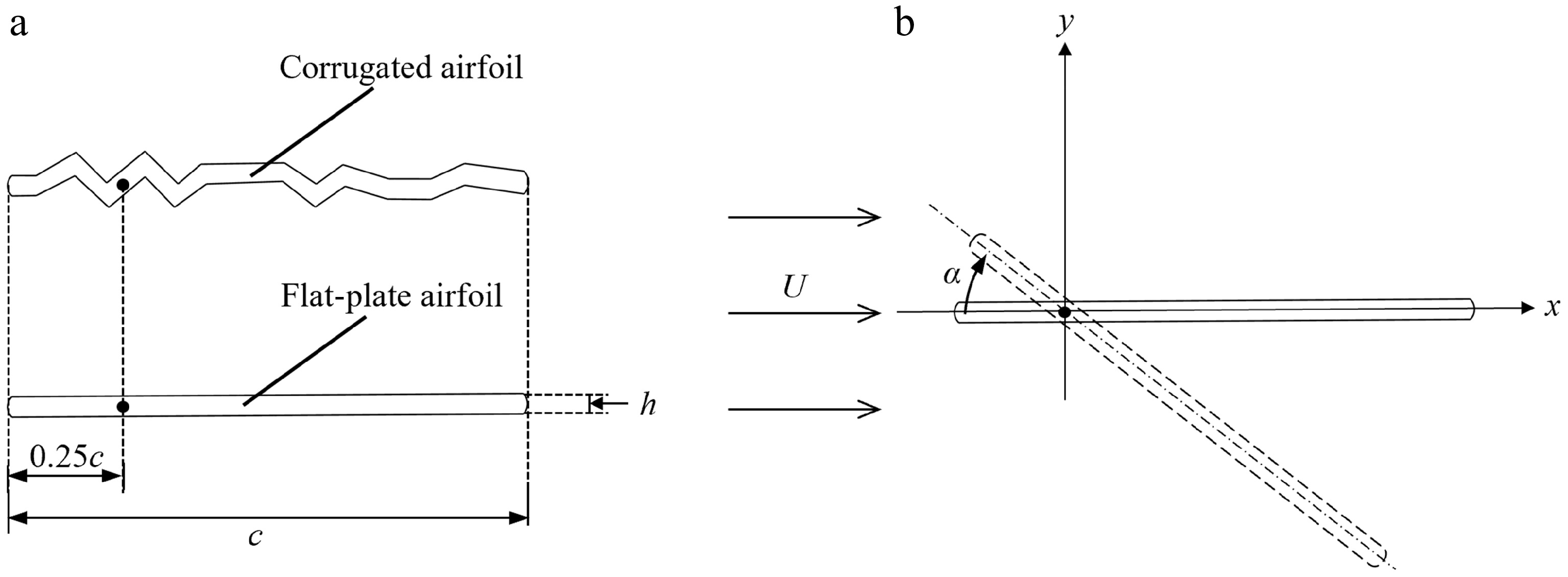
Figure 1.
Schematic of (a) corrugated[17] and flat-plate geometry, and (b) pitching motion.
Both airfoils were defined with c = 100 mm and h = 4 mm. Rounded leading edges were used to reduce the impact of sharp-edged geometry on the surrounding flow. The geometric parameters of the corrugation, such as crest height, trough depth, and spacing, were taken directly from Kesel’s measurements[17].
The airfoils undergo sinusoidal pitching motion around the 25% chord location. The pitching angle α is prescribed as follows:
$ \left.\begin{array}{r} \alpha ={\alpha }_{0}+\dfrac{{\alpha }_{m}}{2}\sin (\omega t),\\ k=\dfrac{\omega c}{2U}, \end{array}\right\} $ (1) where α0 and αm denote the initial angle of attack and the pitching amplitude, respectively. U, k, and ω denote the freestream velocity, reduced frequency, and angular velocity, respectively.
Numerical method
-
Numerical calculations were performed with the finite-volume-based solver ANSYS Fluent. The flow around the airfoil was modeled using the two-dimensional incompressible unsteady Navier–Stokes equations, whose dimensionless form is given below:
$ \left.\begin{array}{c} \mathbf{\nabla }\cdot \boldsymbol{u}=0,\\ \partial \boldsymbol{u}/\partial \textit{t}+\left(\boldsymbol{u}\cdot \mathbf{\nabla }\right)\boldsymbol{u}+\mathbf{\nabla }\textit{p}-{\nabla }^{2}\boldsymbol{u}\textit{/Re}=0, \end{array}\right\} $ (2) where u, t, and p denote the dimensionless velocity, time, and pressure, respectively.
$ \mathbf{\nabla } $ $ {\nabla }^{2} $ For the convective terms, a second-order upwind scheme was used, while for time advancement we used a fully implicit second-order scheme to ensure both temporal accuracy and numerical stability. Pressure–velocity coupling was handled using the SIMPLE algorithm, and turbulence was modeled using the shear stress transport (SST) k–ω model. The SST k–ω model was adopted because it performs well for flows with adverse pressure gradients and local separation while maintaining reasonable computational cost.
The pitching motion was defined using a user-defined function. To achieve the motion, a dynamic mesh approach with diffusion-based smoothing was adopted. A structured mesh was employed near the airfoil surface to better capture viscous flow features, while unstructured triangular cells were applied farther from the surface. This hybrid meshing strategy ensures high mesh quality during mesh motion and maintains computational efficiency by controlling the total cell count. For boundary conditions, a pressure far-field condition was applied at the outer domain to model the open-flow environment, while a no-slip boundary was assigned to the airfoil surface.
The instantaneous lift and drag were obtained by integrating the pressure and wall shear stress along the airfoil surface. The airfoil lift (FL) denotes the component normal to the freestream, and the airfoil drag (FD) is the force component aligned with the freestream direction. In addition, P represents the pressure, P∞ is the pressure from the far field, and T is the pitching period. The force, cycle-averaged force, and aerodynamic pressure coefficients are defined as follows:
$ \mathit{C}_{\mathit{\mathrm{L}}}\mathrm{=}\mathit{F}_{\mathit{\mathrm{L}}}\mathrm{/0.5}\mathit{\rho U}^{\mathrm{2}}\mathit{c,} $ (3) $ \mathit{C}_{\mathit{\mathrm{D}}}\mathrm{=}\mathit{F}_{\mathit{\mathrm{D}}}\mathrm{/0.5}\mathit{\rho U}^{\mathrm{2}}\mathit{c,} $ (4) $ \mathit{C}_{\mathit{\mathrm{P}}}\mathrm{=(}\mathit{P-P}_{\text{∞}}\mathrm{)/0.5}\mathit{\rho U}^{\mathrm{2}}\mathit{,} $ (5) $ \mathit{L/D}\mathrm{=}\mathit{C}\mathrm{_{\mathit{\mathrm{L}}}\mathrm{/\mathit{C}}}_{\mathit{\mathrm{D}}}, $ (6) $ \overline{{C}_{\rm L}}=\dfrac{1}{T}\int \nolimits_{0}^{T}{C}_{\rm L}\left(t\right){\rm{d}}t, $ (7) $ \overline{{C}_{\rm D}}=\dfrac{1}{T}\int \nolimits_{0}^{T}{C}_{\rm D}\left(t\right){\rm{d}}t, $ (8) $ (L/D)_{\text{mean}}=\overline{C_{\mathrm{L}}}/\overline{C_{\mathrm{D}}}. $ (9) Mesh independence and time-step verification
-
To examine the sensitivity to spatial resolution, three different densities of computational meshes were constructed. For the coarse, medium, and fine meshes, the minimum near-wall cell spacing was set to 0.002c, 0.0013c, and 0.0009c, respectively. These spacings yielded approximately 0.09, 0.20, and 0.45 million cells across the entire computational domain. The medium mesh is shown in Fig. 2 as an example. Simulations were performed at Re = 34,000, k = 0.1, with α0 = 10° and αm = 20°. For the chosen α0 and αm, the corresponding pitching angle ranges from 0° to 20°. The instantaneous lift and drag coefficients over two cycles, together with the surface pressure distribution at α = 10°, are compared for the three meshes in Fig. 3. As shown in Fig. 3, the lift, drag, and surface pressure coefficient curves from the medium and fine meshes nearly coincide. Quantitatively, the relative variations in the mean lift and drag coefficients between the medium and fine grids are approximately 0.34% and 0.59%, respectively. Therefore, considering the trade-off between numerical accuracy and computational efficiency, the medium mesh is selected for the subsequent simulations.
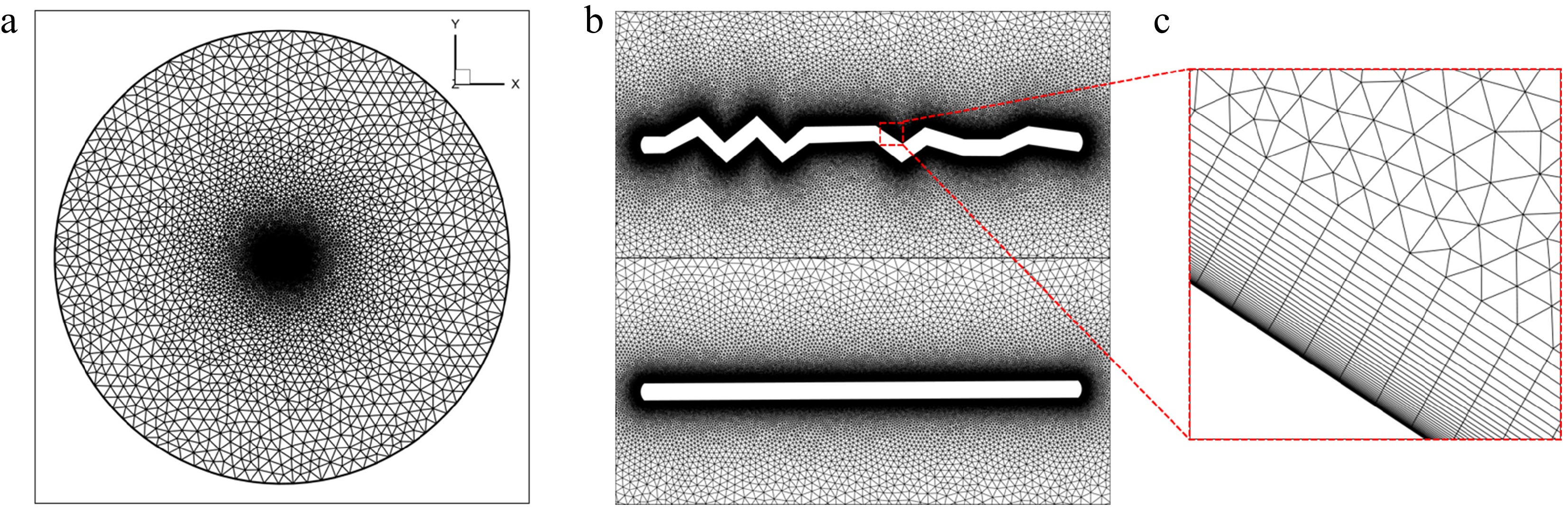
Figure 2.
Portions of the O-type unstructured computational mesh: (a) in the computational domain, (b) around the two airfoils, and (c) in the locally refined region near the corrugated airfoil.
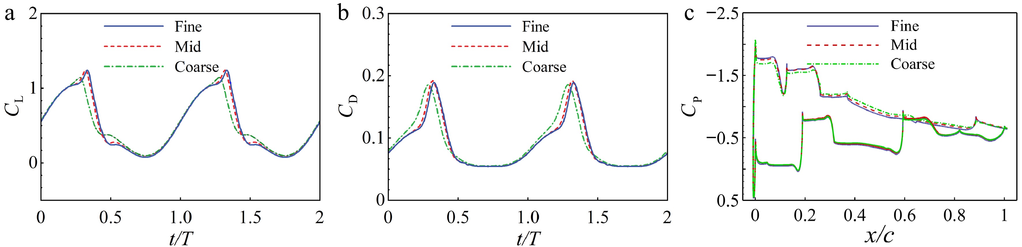
Figure 3.
(a) Variation of CL, (b) variation of CD, and (c) variation of surface CP with different densities of meshes at t/T = 0.5.
To evaluate the effect of temporal resolution on simulation accuracy, the simulations were repeated on the medium mesh with 200, 400, and 800 time steps per pitching cycle. The difference in mean lift coefficient across the three cases was less than 1%, indicating that using at least 200 time steps per pitching cycle was sufficient for temporal convergence, as summarized in Table 1. To strike a balance between numerical accuracy and computational cost, a total of 400 time steps per cycle were adopted for all subsequent simulations. This temporal resolution provides a sufficient margin well within the converged regime relative to the converged threshold (T/200), while avoiding the excessive computational expense associated with 800 time steps per cycle.
Table 1. Mean lift coefficient for different time-step sizes.
Mesh Time steps per cycle Cell count $ \overline{C_{\mathrm{L}}} $ 200 0.513 Medium 400 0.24 million 0.516 800 0.517 Solver validation
-
Figure 4 shows the computed steady aerodynamic coefficients of the corrugated airfoil over a range of angles of attack at Re = 34,000 and U = 5 m/s. The results were compared with those of Barnes and Visbal[22] to verify the accuracy of the present numerical method. Over the angle-of-attack range from 5° to 10°, the aerodynamic coefficients obtained in this study remain in close agreement with the results of Barnes and Visbal. This favorable comparison validates the capability of the present method to accurately resolve the flow over the complex geometry of the corrugated airfoil.
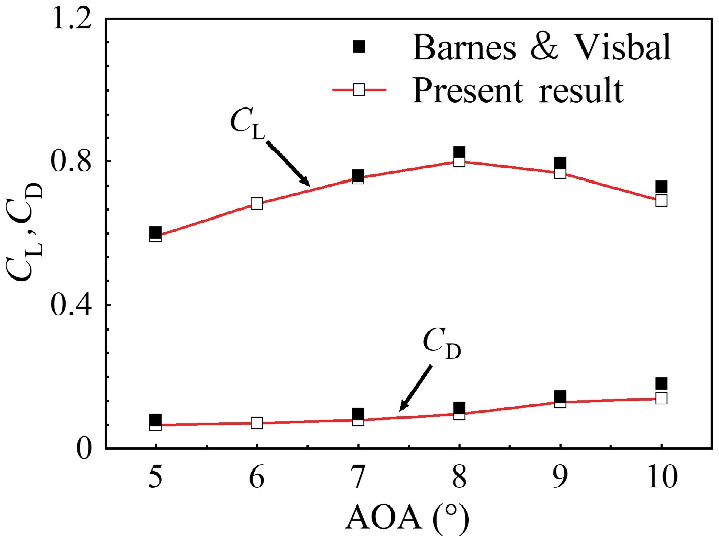
Figure 4.
Steady lift and drag coefficients at angles of attack from 5° to 10°.
The wind-tunnel experimental results of McAlister et al.[32] were used to further validate the capability of the present solver in simulating unsteady dynamic stall. Both the mild and deep dynamic stall of a NACA 0012 airfoil were validated. For the mild-stall case, the validation was performed at Ma = 0.6, k = 0.081, and α = 3.2° + 4.6°sin(ωt). For the deep-stall case, the corresponding conditions were Ma = 0.283, k = 0.151, α = 14.91° + 9.88°sin(ωt). Figure 5a, b shows the hysteresis loops of CL with the angle of attack for the two conditions, respectively. Close agreement with the reference data was achieved, validating the reliability of the present solver in both mild and deep stall.
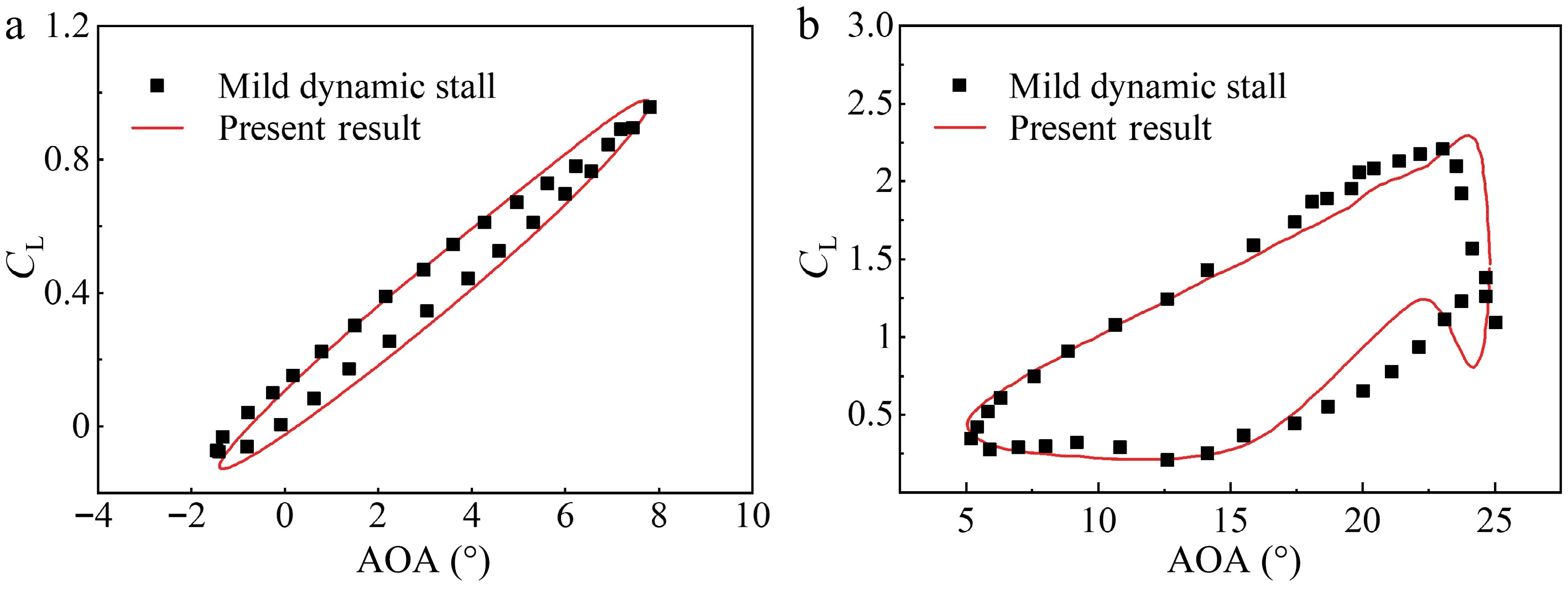
Figure 5.
Validation of lift coefficient against experimental data for (a) mild dynamic stall and (b) deep dynamic stall.
-
To assess the aerodynamic influence of corrugation during dynamic stall, the aerodynamic responses of the corrugated airfoil and the flat-plate airfoil were examined at Re = 34,000 and k = 0.1. The motion parameters were α0 = 10° and αm = 20°, corresponding to a pitching angle of α = 0°−20°. Figure 6 plots the variations of lift and drag coefficients with the pitching angle for the corrugated and flat-plate airfoils.
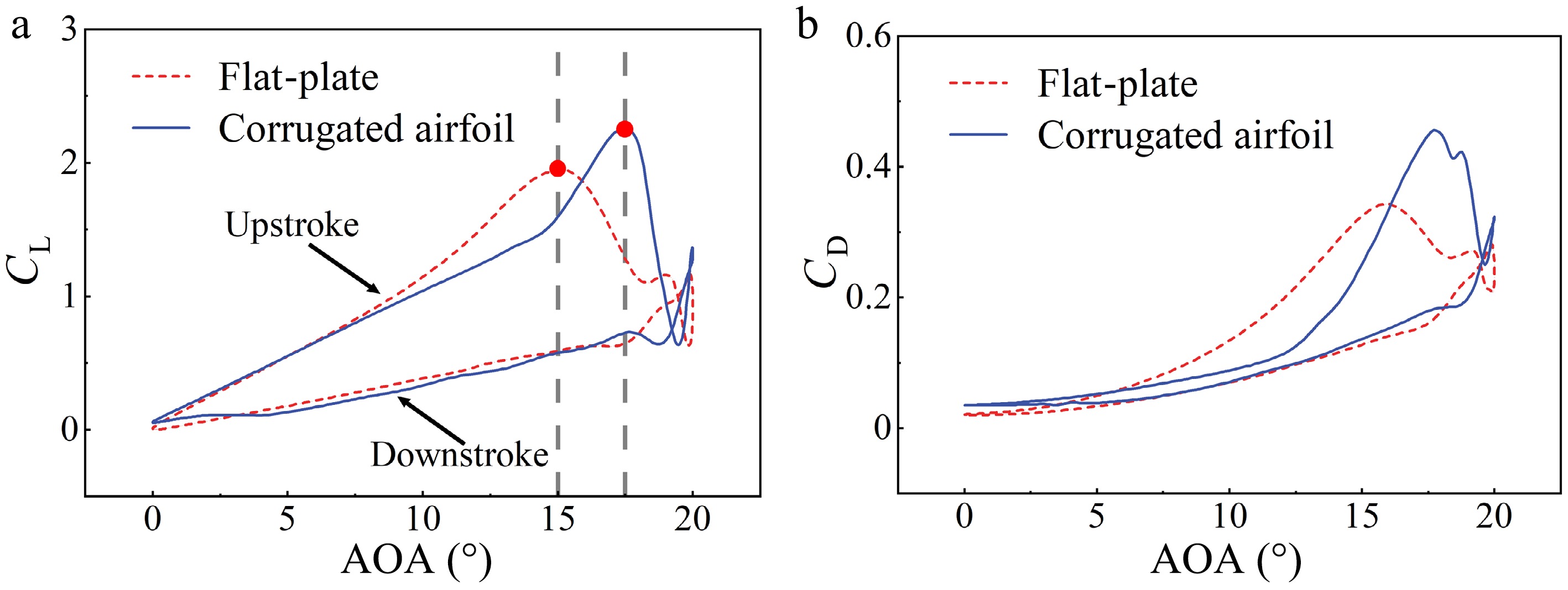
Figure 6.
Variations of (a) lift coefficient and (b) drag coefficient with the pitching angle for corrugated and flat-plate airfoils.
The overall variations of the lift and drag coefficients with the pitching angle exhibit hysteresis loops, which can be divided into upstroke and downstroke phases (Fig. 6a, b). During the upstroke phase, both airfoils experience a gradual increase in aerodynamic lift and drag (Fig. 6a). Within the pitching angle range of about 8°−15°, the flat-plate airfoil exhibits a higher CL than the corrugated airfoil. At higher angles, its lift coefficient falls below that of the corrugated configuration. The flat-plate airfoil reaches its maximum lift at α ≈ 15°, whereas the corrugated airfoil reaches its peak at α ≈ 17.5°, which is noticeably higher. This indicates that the corrugated airfoil can delay stall and enhance maximum aerodynamic forces under unsteady motion relative to the flat plate. During the downstroke phase, the differences in lift between the two profiles diminish. The drag coefficient shows a broadly similar overall trend to the lift coefficient (Fig. 6b).
To elucidate the relationship between instantaneous aerodynamic forces and the underlying flow structures, contours of turbulent kinetic energy (TKE) and vorticity were examined at representative upstroke angles, as shown in Fig. 7a and b, respectively. The TKE contours highlight regions of elevated turbulence intensity, whereas the vorticity contours reveal the evolution of coherent vortices. Together, these flow visualizations help explain the unsteady force generation observed during the upstroke phase.
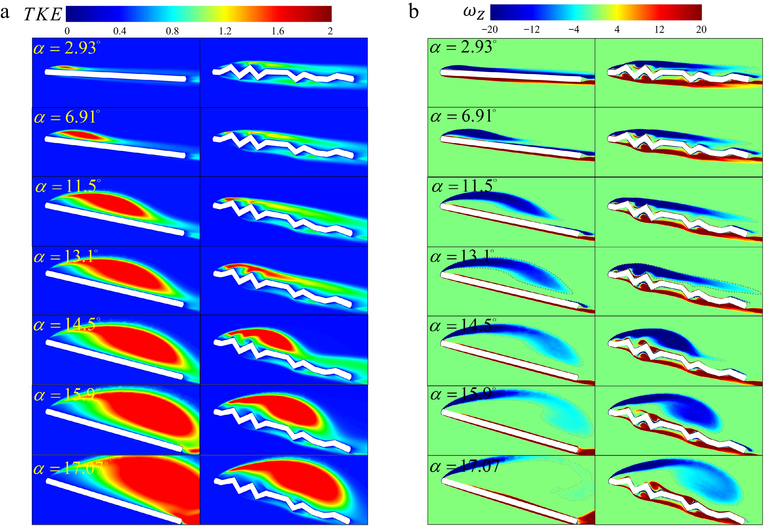
Figure 7.
Dimensionless (a) turbulent kinetic energy (TKE) and (b) spanwise vorticity ($ {\omega }_{Z} $) contours at the upstroke phase of the pitching angle.
Figure 7a shows that the corrugated airfoil exhibits a lower TKE level than the flat-plate airfoil at the same pitching angle, with elevated TKE confined locally within the corrugation troughs rather than forming a continuous high-TKE region. This behavior indicates that the growth of TKE over the corrugated airfoil is slower, and that it is a gradual transition process compared with that over the flat-plate airfoil. The flow over the flat plate remains relatively smooth as the pitching angle increases, and the leading-edge vortex (LEV) enlarges progressively and shifts downstream (Fig. 7b). Meanwhile, the corrugated airfoil generates discrete small-scale vortices in the near-wall region as the pitching angle rises, particularly around the peaks and valleys of the corrugations, as shown at α < 11.5°. As the pitching angle increases to α = 13.1°, these small vortices begin to merge with one another. With a further increase in the angle of attack, the LEV undergoes overall separation as it does on the flat plate. Although the overall development of the LEV on the corrugated airfoil follows a trend similar to that of the flat-plate airfoil, it remains more tightly attached to the surface at the respective instants of time, and its downstream evolution proceeds more slowly.
Moreover, in the velocity magnitude and streamline plots (Fig. 8), multiple small-scale vortices are induced within the troughs of the corrugations at low to moderate angles (α = 2.93°−11.5°). These trapped vortices generate a "virtual contour" effect, as previously described in steady-flow studies[16,19], effectively delaying the merging of vortices trapped within adjacent corrugation troughs, as seen in Fig. 8 at α = 11.5°. As the pitching angle increases to α = 13.1°, the vortices trapped in the fore-corrugation region begin to merge (Fig. 8). This interaction initiates the formation of a merged and compressed recirculation region over the front corrugations, while the separated vortex of the flat plate develops into a larger coherent structure that covers most of the upper surface, as shown in Fig. 8 for α = 13.1°. Notably, this merging occurs at a higher pitching angle than in the steady-flow results of Barnes and Visbal[22], suggesting that unsteady pitching motion shifts the onset of this interaction to higher angles. With a further increase in the angle of attack, the LEV over the corrugated airfoil separates as a coherent structure, but less strongly than that over the flat plate.
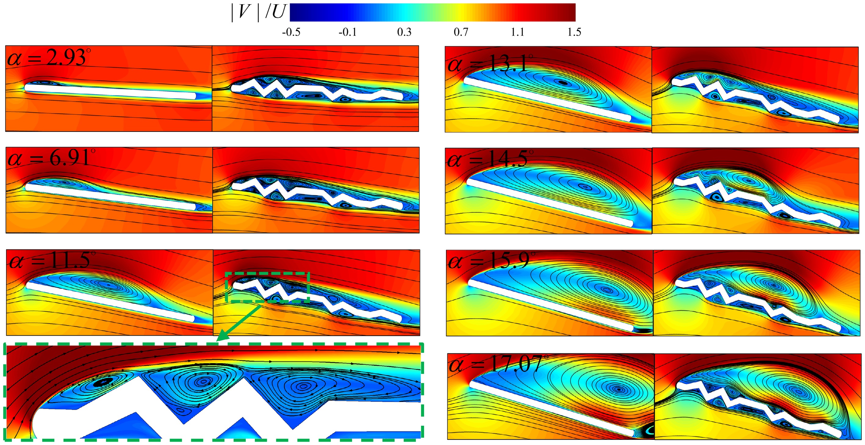
Figure 8.
Dimensionless velocity magnitude ($ |V|/U $) and streamline contours at the upstroke phase of the pitching angle and local enlarged view at α = 11.5°.
To further quantify the degree of LEV separation, the center of the closed streamline region associated with the leading-edge separated vortex is defined as the vortex-core position in this study. The relative position of the vortex core with respect to the leading-edge endpoint, normalized by the chord length, is defined as xcore/c for the chordwise position and ycore/c for the normal position. These two quantities are used to quantify the development and detachment of the LEV. Since a clearly identifiable, coherent primary separated vortex is formed above the corrugated airfoil only at higher angles of attack, vortex-core positions are reported only for α = 14.5°, 15.9°, and 17.07°, as shown in Fig. 9. Within the higher-angle range considered, the vortex core of the corrugated airfoil remains consistently closer to the leading edge and the airfoil surface. This indicates that both the development and detachment of the LEV proceed more slowly than on the flat plate, further confirming that the corrugated airfoil exhibits a weaker separation.
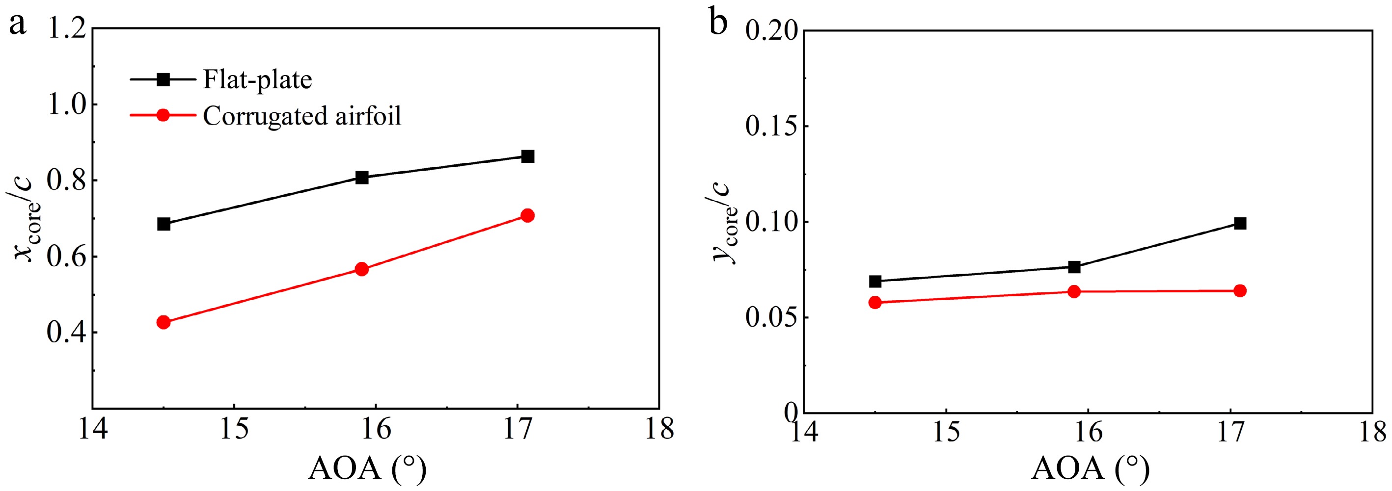
Figure 9.
Vortex-core coordinates relative to the leading-edge point for the flat-plate and corrugated airfoils at different angles of attack: (a) xcore/c and (b) ycore/c.
The differences in vortex evolution between the two airfoils directly contribute to the differences in their aerodynamic response. Figure 10 presents the instantaneous flow fields and surface pressure distributions at the instant of maximum lift for each airfoil. During the stall process, the corrugated airfoil retains stronger suction and less extensive separation compared with the flat-plate airfoil. For example, at α = 14.5°, where the flat plate reaches peak lift, its LEV has already developed into a structure covering the whole upper surface of the airfoil. Consequently, the region of negative pressure occupies most of the upper surface (Fig. 10a, b). Nevertheless, the corrugated airfoil exhibits a less-developed LEV and reduced flow separation on the surface, leading to weaker suction near x/c ≈ 0.6 (Fig. 10c). As a result, the lift of the corrugated airfoil is lower at this instant. At α = 17.1°, where the corrugated airfoil reaches its peak lift, the covering area of the LEV extends to the trailing edge, resulting in a stronger suction peak and higher lift compared with the flat plate (Fig. 10c), whose LEV has already detached from the surface. The drag exhibits a similar trend: due to delayed vortex shedding, the corrugated airfoil exhibits a later and higher drag peak. Under the low reduced-frequency conditions considered in this study, the aerodynamic improvement of the corrugated airfoil is mainly attributed to LEV evolution, while the influence of the wake on the aerodynamic forces is relatively small[33−35]. Therefore, the present analysis focuses on LEV evolution, and wake dynamics or trailing-edge vortex shedding is not treated separately as a dominant mechanism.
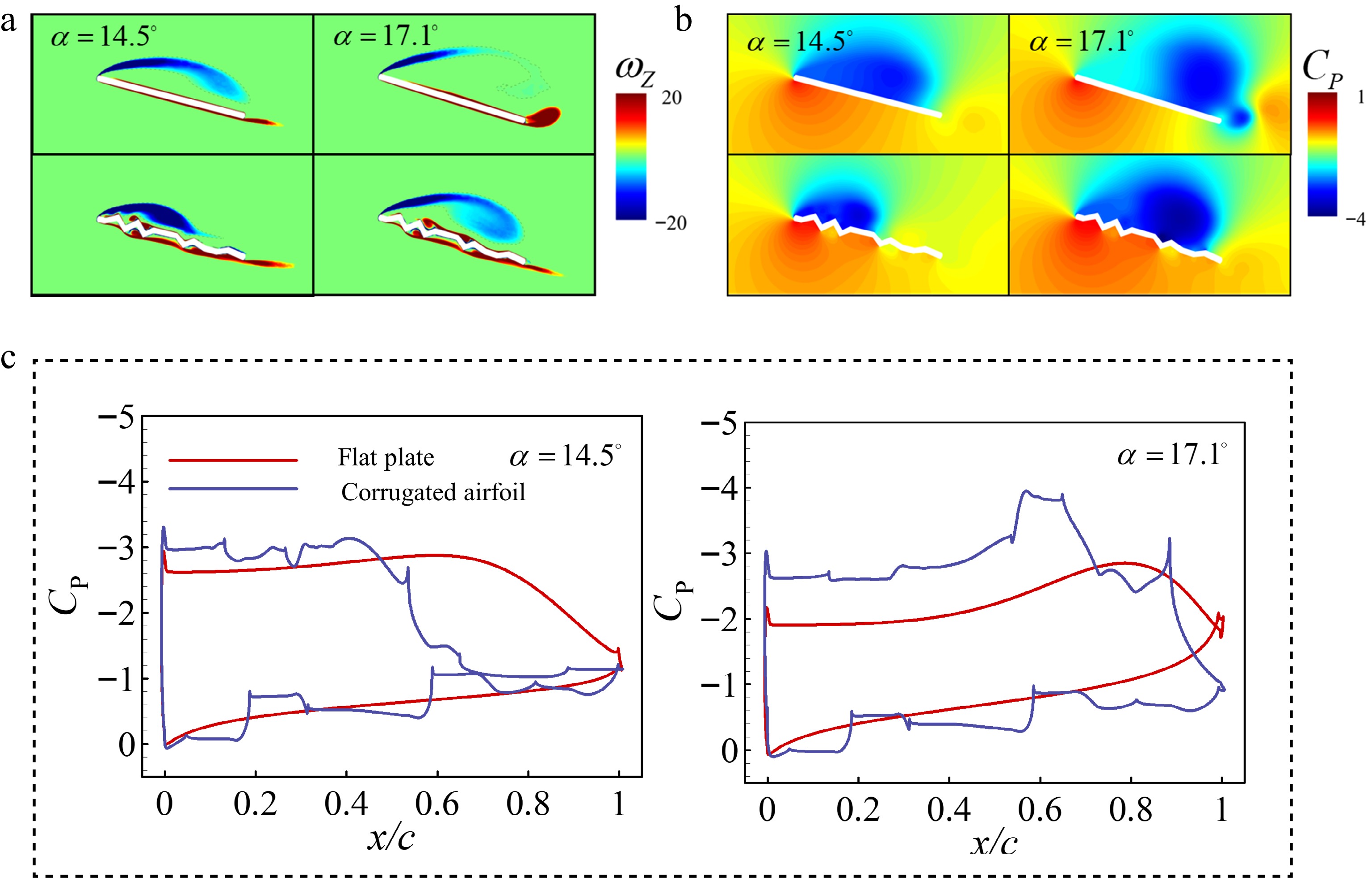
Figure 10.
(a) Dimensionless spanwise vorticity contours, (b) pressure coefficient contours, and (c) chordwise pressure coefficient of corrugated and flat-plate airfoils at pitching angles of 14.5° and 17.1°, respectively.
Collectively, under the pitching conditions of k = 0.1, α0 = 10°, and αm = 20°, the corrugated airfoil demonstrates a clear advantage in delaying stall and increasing the maximum lift coefficient relative to the flat-plate airfoil. This advantage stems from the peak-trough geometry of the corrugated airfoil, which localizes TKE production and induces trough vortices that keep the LEV more attached to the surface, thereby delaying vortex-merging-induced separation to a higher pitching angle.
Influence of reduced frequency
-
To investigate the effects of reduced frequency (k) on the aerodynamic response and flow-field characteristics, both airfoils were tested for various k at Re = 34,000 with a pitching amplitude of αm = 20° and α0 = 10°. Based on previous studies, conditions of k < 0.05 can be regarded as quasi-steady,[31] whereas higher values produce notable unsteady effects. Therefore, four reduced frequencies, k = 0.02, 0.05, 0.1, and 0.2, were considered. This range covers conditions from quasi-steady motion to significantly unsteady pitching, representative of scenarios from slow attitude adjustments to rapid maneuvers in MAV operations.
Lift and drag coefficient histories for each k are presented in Fig. 11a and b. For both airfoils during the upstroke phase (t/T = 0−0.5), increasing k leads to higher lift and drag coefficient peaks and larger stall angles. At the same k, the corrugated airfoil generally exhibits higher stall angles and higher lift and drag peaks than the flat plate. At k = 0.2, however, the corrugated airfoil exhibits nearly the same stall angle as the flat plate, but a lower peak lift. This behavior can be linked to the partially developed LEV before reaching the maximum angle of attack, as will be discussed later in this paper. The peak lift and drag for a given airfoil occur almost simultaneously, suggesting only a small phase difference between them at the relatively low k values considered here. During the downstroke, higher k cases exhibit a steeper slope and more pronounced fluctuations in the lift coefficient, indicating stronger unsteady effects in the lift response at higher reduced frequencies.
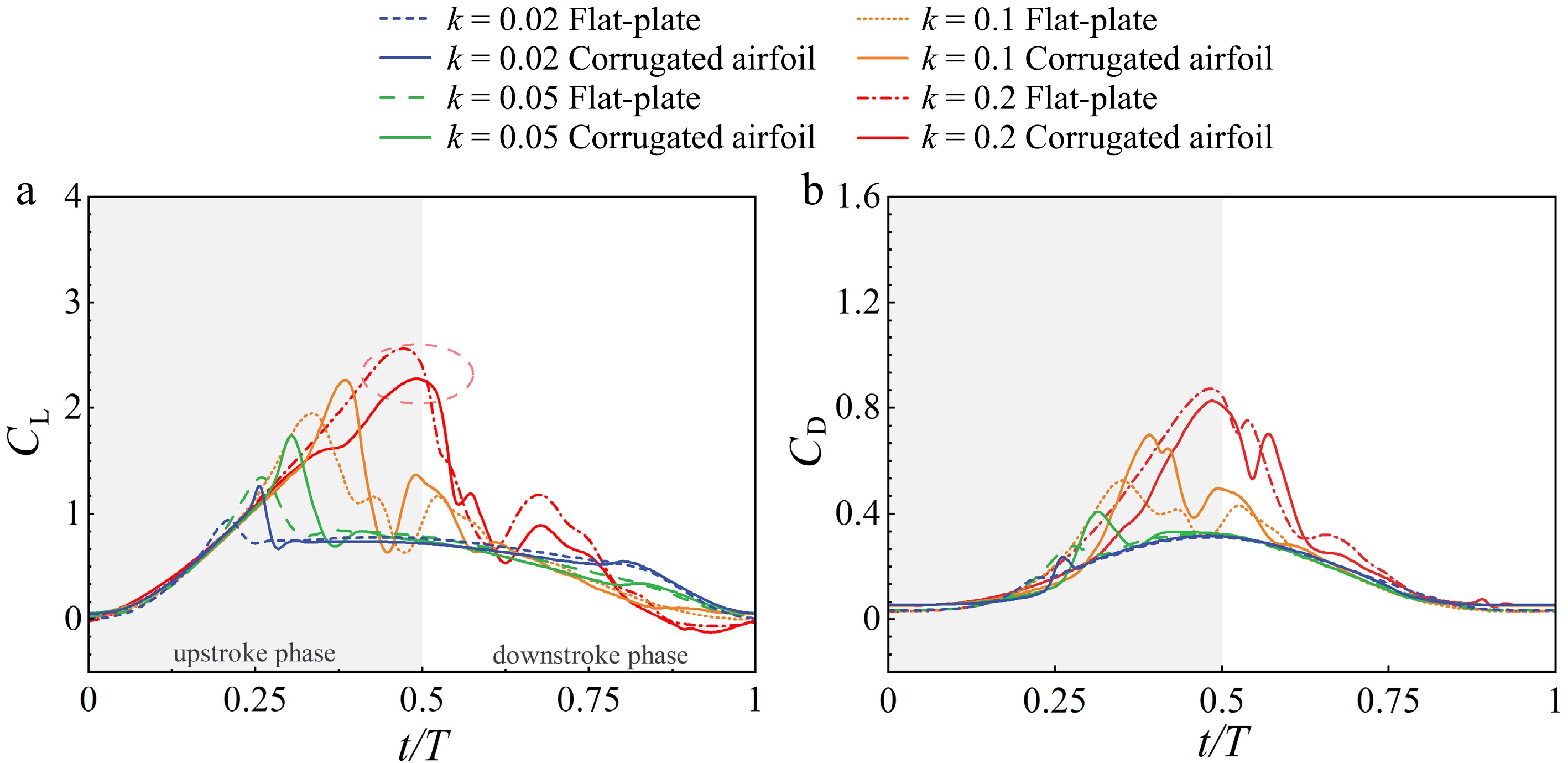
Figure 11.
Histories of (a) CL and (b) CD for the corrugated and flat-plate airfoils at k = 0.02, 0.05, 0.1, and 0.2.
To relate force behavior to flow structures, instantaneous spanwise vorticity fields were compared at identical pitching angles for different k values, as shown in Fig. 12. With increasing k, the LEV for both airfoils remains more attached to the surface at the same pitching angle, indicating that the development of vortex shedding is delayed. The corrugated airfoil consistently shows a delayed detachment of LEV compared with the flat-plate airfoil. For example, under the conditions of k = 0.2, α = 10°, 14.5°, or 19.8°, the LEV on the corrugated airfoil remains more tightly attached to the airfoil surface (Fig. 12).
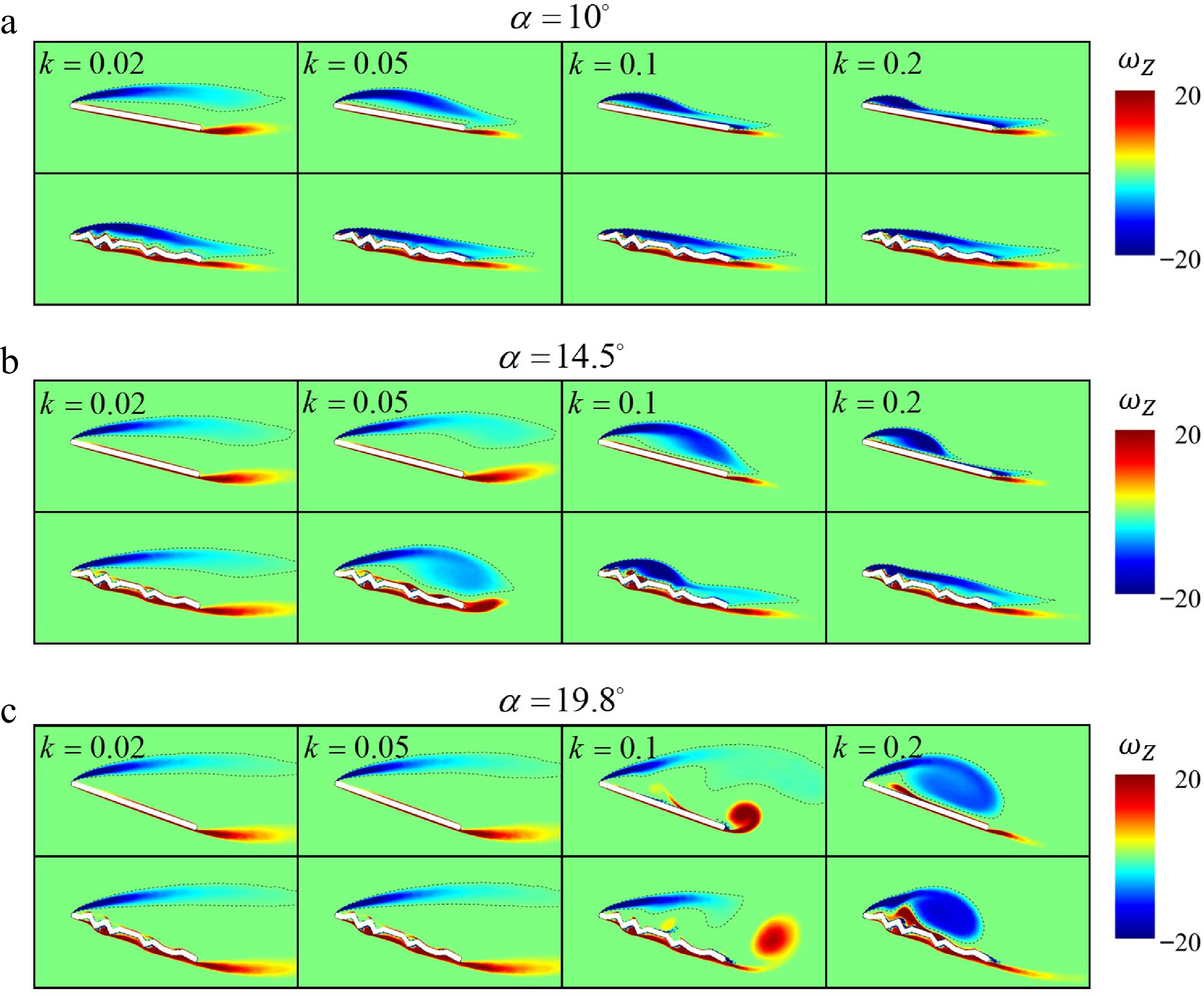
Figure 12.
Dimensionless spanwise vorticity contours of the corrugated and flat-plate airfoils at (a) α = 10°, (b) 14.5°, and (c) 19.8° for k = 0.02, 0.05, 0.1, and 0.2.
Figure 13 provides further insight by examining the vorticity and pressure fields at the instant of maximum lift for each. With increasing k, the LEV develops closer to the airfoil surface and covers more of the upper surface, thereby enhancing suction (Fig. 13a, b). This increased suction, combined with relatively minor changes in lower-surface pressure, leads to higher lift coefficients at larger k, as shown in Fig. 14a−d. Compared with the flat-plate airfoil, the vortex over the corrugated airfoil stays closer to the suction surface and shows a weaker tendency to separate. In addition, the pressure distributions along the airfoil surface follow a pattern broadly consistent with that described in the section "Influence of corrugation on dynamic stall" (Fig. 10c), when each airfoil attains its maximum lift.
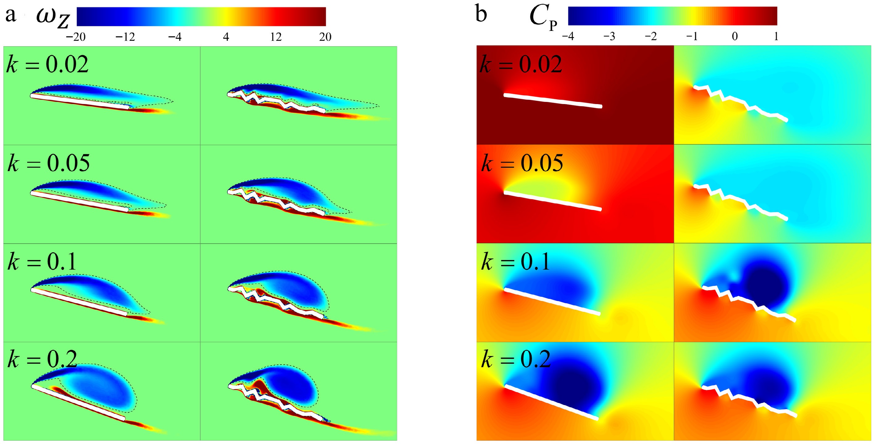
Figure 13.
Contours of (a) spanwise vorticity and (b) pressure coefficient at the peak lift for both the corrugated and flat-plate airfoils at k = 0.02, 0.05, 0.1, and 0.2.
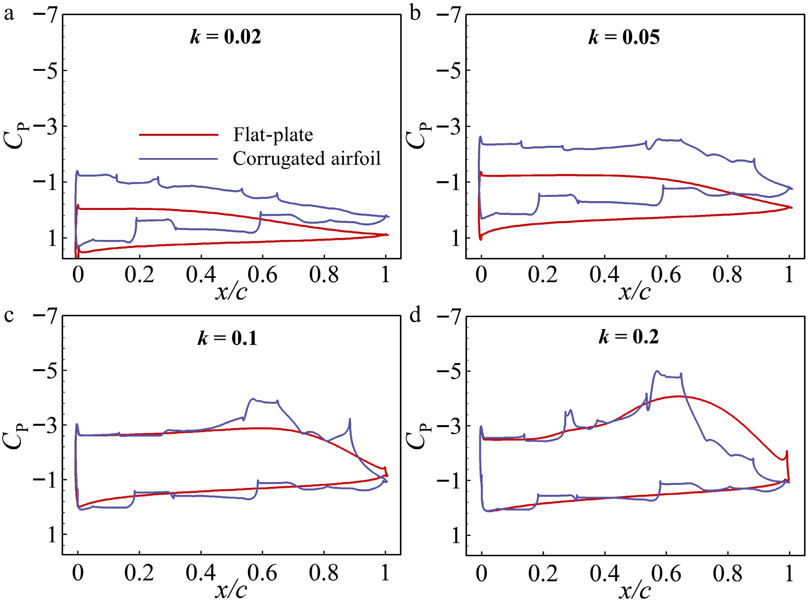
Figure 14.
Chordwise pressure coefficient distributions at the maximum angle (α = 20°) for the flat-plate and corrugated airfoils from k = 0.02 to 0.2 in panels (a)−(d).
As mentioned before, an exception was observed for the corrugated airfoil at k = 0.2, with a peak lift lower than that of the flat-plate airfoil (Fig. 11a). To explain this behavior, Fig. 15 provides an analysis of the flow field before and after the stall angle. It reveals that, at α = 19.5° during the upstroke phase (Fig. 15a), the flat-plate airfoil is almost fully covered by the LEV on its suction surface, while the LEV of the corrugated airfoil develops more slowly and has not yet reached the trailing edge. This behavior of delayed development of LEV for the corrugated airfoil is consistent with smaller k cases. However, as the motion approaches the peak angle (α = 20°), the pitching rate decreases to zero, leading the flow to exhibit a more quasi-steady behavior, and the LEV of the corrugated airfoil ceases to develop. Under this condition, the LEV generated by the corrugated airfoil loses the benefit of unsteady stabilization and detaches earlier, before it is fully developed. As a result, at α = 19.5° during the downstroke phase (Fig. 15b), the LEV of the corrugated airfoil is not fully developed, with reduced strength and coherence as it sheds away from the surface, leading to a reduced instantaneous lift.
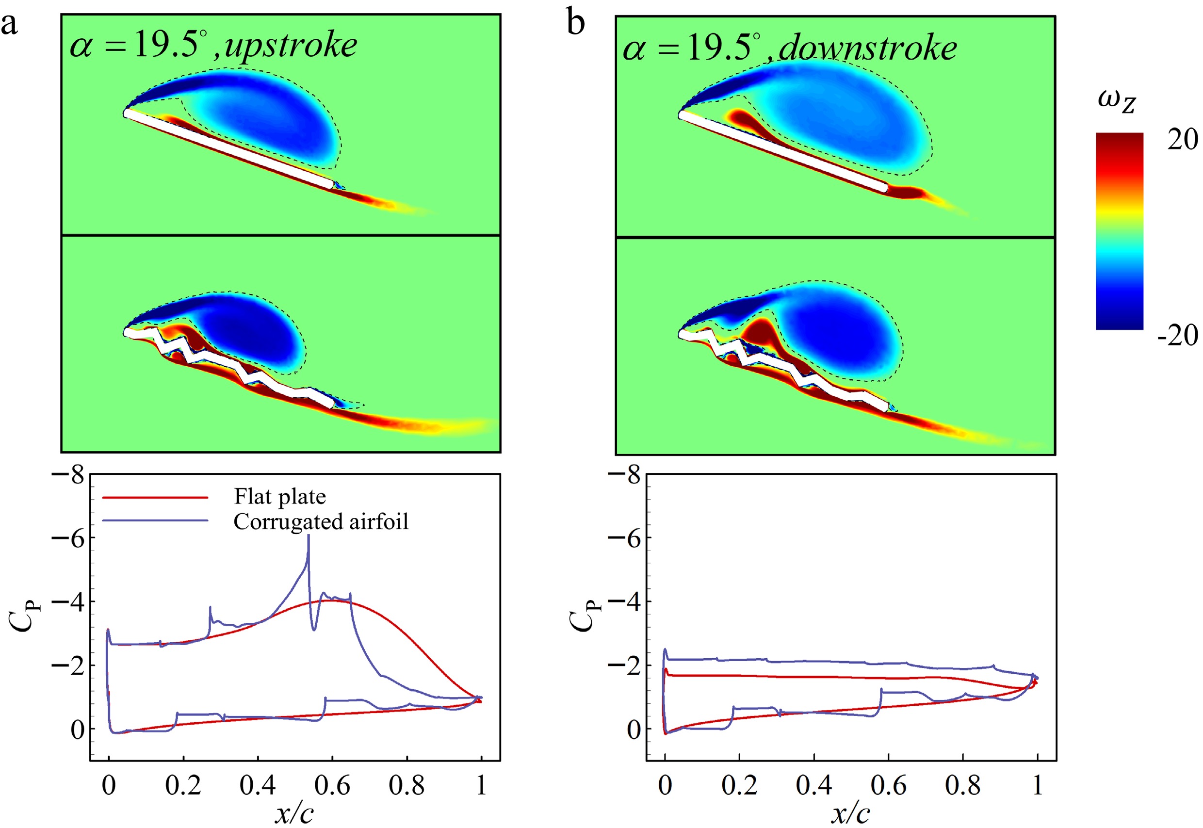
Figure 15.
Contours of dimensionless spanwise vorticity and chordwise pressure coefficient distributions at α = 19.5°, where the angle of attack approaches its maximum α = 20° during (a) upstroke and (b) downstroke phases.
Overall, the corrugated airfoil exhibits a delayed stall relative to the flat plate. This behavior is consistent with the observations in the section “Influence of corrugation on dynamic stall,” and it also persists across most of the reduced frequencies examined, except for the high-k condition discussed above. We speculate that further increasing the pitching amplitude would still lead to the advantage of the corrugated airfoil, namely delayed stall and an enhanced peak lift coefficient.
Influence of the pitching angle range
-
The effect of the pitching angle range on aerodynamic performance was examined at k = 0.05 and Re = 34,000. Three pitching amplitudes were considered: αm1 = 10°, αm2 = 20°, and αm3 = 30°, corresponding to α = 0°−10°, α = 0°−20°, and α = 0°−30°. Figure 16 compares the lift and drag coefficient histories of the two airfoils.
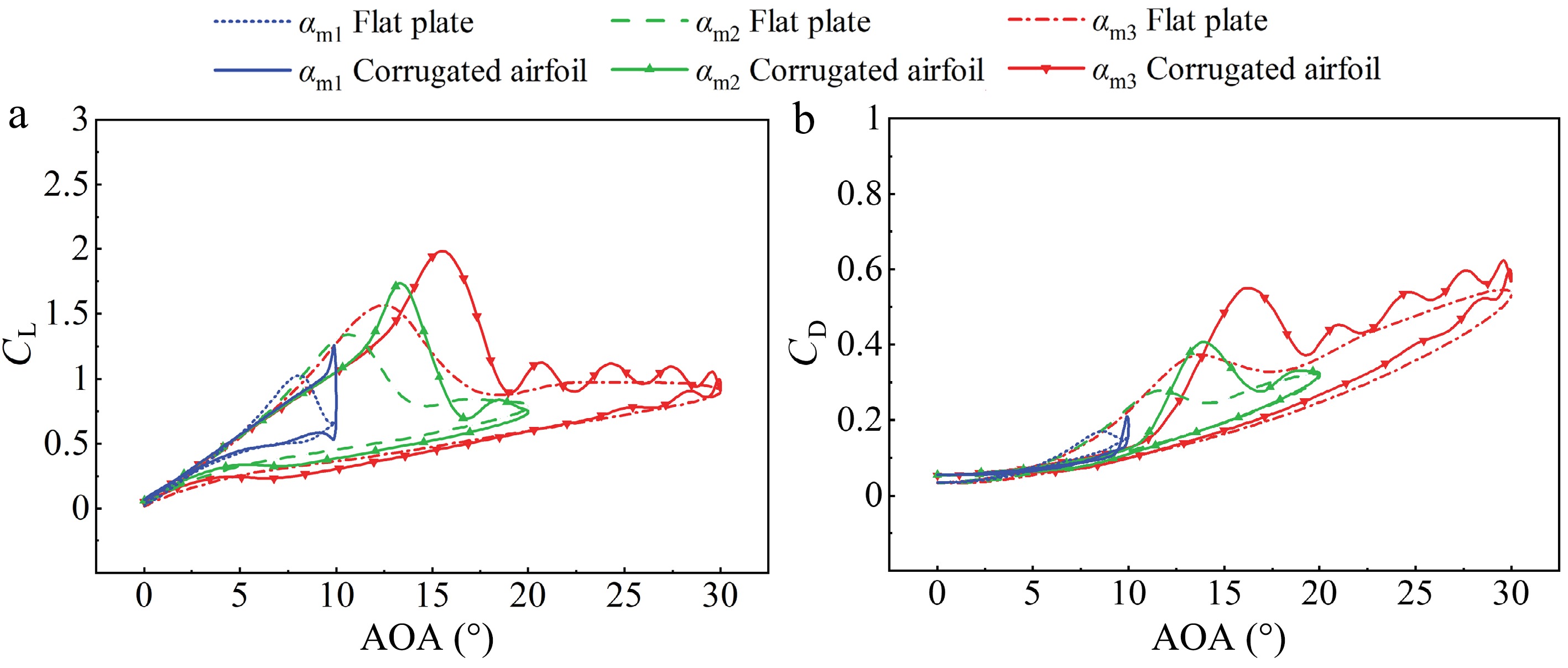
Figure 16.
Hysteresis loops of (a) lift coefficient and (b) drag coefficient for the corrugated and flat-plate airfoils at αm1 = 10°, αm2 = 20°, and αm3 = 30°.
As shown in Fig. 16, for both airfoils, increasing the pitching angle leads to higher stall angles and peak lift and drag coefficients. This trend is consistent with the findings of previous studies[13,35−37]. In general, the hysteresis loop for a given airfoil remains similar in shape at larger pitching amplitudes, whereas the enclosed area increases with amplitude, indicating stronger unsteady effects. Across all amplitudes tested, the corrugated airfoil maintains a higher stall angle and lift peak than the flat plate, consistent with the behavior described in the section “Influence of corrugation on dynamic stall.” During the upstroke phase, stronger LEV and delayed separation jointly contribute to higher lift peaks and later stall onset at larger amplitudes. During the downstroke phase, the lift and drag responses of the corrugated airfoil are comparable to those of the flat-plate airfoil over the range of amplitudes considered.
Flow-field observations during the upstroke phase in Fig. 17 show that, at α = 8.5°, the extent of LEV separation decreases with increasing pitching amplitude for both airfoils, indicating that larger pitching amplitudes delay the onset of separation. At α = 15°, this trend in LEV development for the cases of αm3 = 30° and αm2 = 20° becomes more pronounced. The αm3 = 30° case maintains a stronger and less detached LEV than the αm2 = 20° case, which corresponds to the higher lift level in Fig. 16a. At the same angle of attack, under different pitching-amplitude conditions, the LEV over the corrugated airfoil consistently exhibits less separation than that over the flat plate, indicating that the corrugated airfoil still maintains a stall-delaying effect.
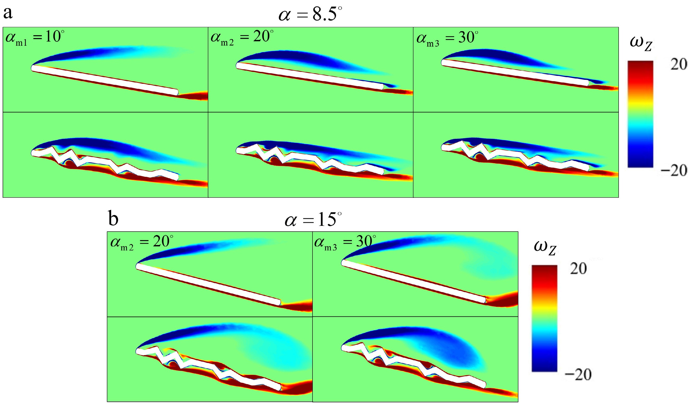
Figure 17.
Contours of dimensionless spanwise vorticity (illustrated for [a] α = 8.5° and [b] α = 15°) for the corrugated and flat-plate airfoils at αm1 = 10°, αm2 = 20°, and αm3 = 30°.
Overall, increasing the pitching amplitude intensifies the unsteady aerodynamic response and promotes stronger vortex development, while the corrugated airfoil still retains its advantages of delayed stall and higher peak lift under the studied conditions.
The instantaneous aerodynamic responses indicate that the corrugated airfoil generally retains delayed-stall characteristics over a range of reduced frequencies and pitching amplitudes. Nevertheless, the corresponding cycle-averaged force characteristics have not yet been clarified. This trade-off will be further discussed in the following section.
Mean forces
-
The instantaneous-force analysis in the section “Influence of corrugation on dynamic stall” demonstrated that the corrugated airfoil exhibits delayed stall and a higher maximum lift compared with the flat plate, and these effects are influenced by both reduced frequency and pitch amplitude. However, instantaneous forces alone do not provide a direct quantitative assessment of the overall aerodynamic performance. Therefore, mean aerodynamic coefficients are introduced as performance metrics.
Figure 18 summarizes the cycle-averaged aerodynamic coefficients of both airfoils over the tested reduced frequencies and pitch amplitudes. According to Fig. 18, when the pitch amplitude is fixed, both
$ \overline{C_{\mathrm{L}}} $ $ \overline{C_{\mathrm{D}}} $ $ \overline{C_{\mathrm{L}}} $ $ \overline{C_{\mathrm{D}}} $ 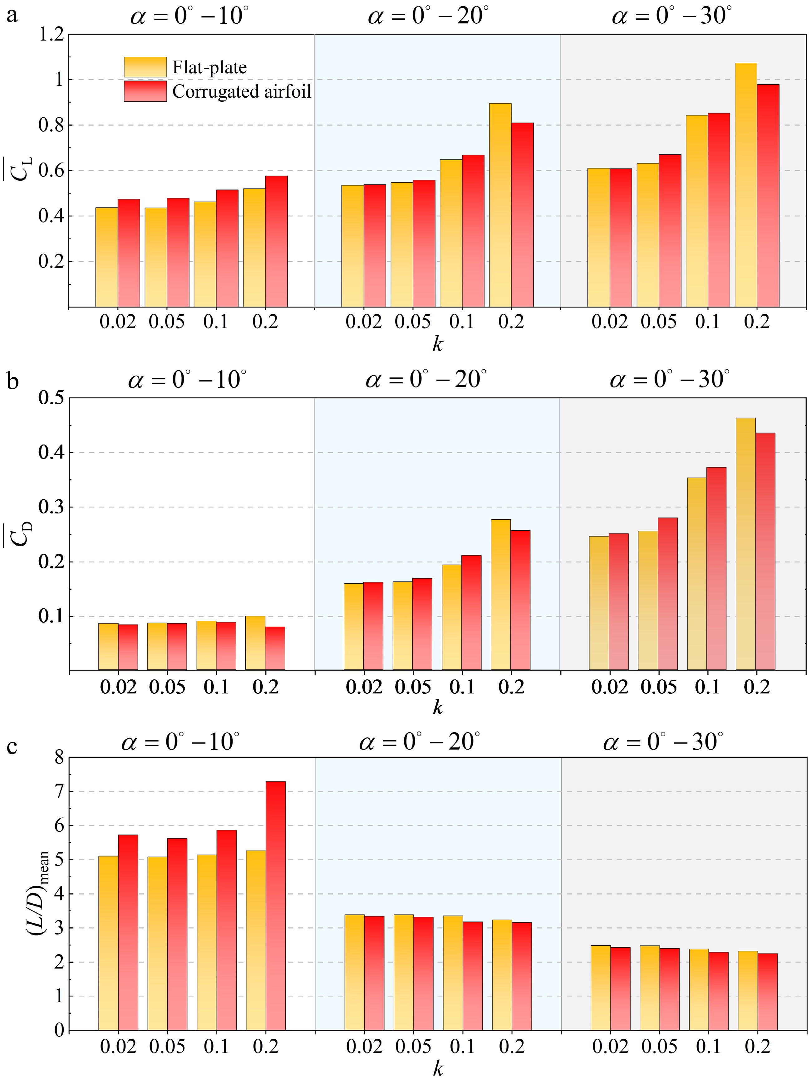
Figure 18.
Averaged values of lift, drag, and lift-to-drag ratio for the corrugated and flat-plate airfoils under different k and ranges of α: (a) lift, (b) drag, and (c) lift-to-drag ratio.
A comparison of the aerodynamic behavior between the corrugated and flat-plate airfoils is given in Table 2. When α = 0°−10° and k = 0.2, the corrugated airfoil achieves the highest relative gain (approximately 38%) in (L/D)mean compared with the flat-plate airfoil among the originally tested cases. The cycle-averaged CL of the corrugated airfoil increases by approximately 10%, compared with that of the flat-plate airfoil.
Table 2. Cycle-averaged aerodynamic behavior of different k for α = 0°−10°.
k Airfoil type $ \overline{C_{\mathrm{L}}} $ $ \overline{C_{\mathrm{D}}} $ (L/D)mean 0.02 Flat-plate 0.437 0.086 5.107 Corrugated 0.474 0.083 5.725 0.05 Flat-plate 0.436 0.086 5.117 Corrugated 0.479 0.085 5.624 0.1 Flat-plate 0.462 0.090 5.143 Corrugated 0.515 0.088 5.865 0.2 Flat-plate 0.520 0.099 5.263 Corrugated 0.576 0.079 7.289 Overall, under the tested conditions, the results indicate that the corrugated airfoil exhibits a relatively pronounced advantage in the mean lift-to-drag ratio over the flat plate for α = 0°−10°, and achieves the highest mean lift-to-drag ratio at k = 0.2. The conditions tested in this study are close to typical MAV operating states, such as gust response, attitude adjustment, and moderate maneuvering. These results provide a reference for MAV wing design and operating-parameter selection within the investigated range. It should also be noted that dynamic stall is not fully developed in some of the cases considered in the study. The interpretation of the results should be limited to the present range of investigated conditions.
-
This study numerically investigated the aerodynamics of a two-dimensional dragonfly-inspired corrugated airfoil undergoing pitching motion, with a flat-plate airfoil for comparison. Simulations were performed over reduced frequencies (k = 0.02−0.2) and pitching angle ranges (α = 0°−10°, α = 0°−20°, and α = 0°−30°) at Re = 34,000. These conditions were chosen to reflect practically relevant pitching scenarios, although fully developed dynamic stall may not occur in every case. Aerodynamic performance and flow-field differences between the two types of airfoil were analyzed to quantify the advantages of corrugation relative to those of a flat plate. This study also identified the conditions under which the corrugated airfoil exhibits relatively favorable cycle-averaged aerodynamic performance within the investigated low-frequency range, providing reference data for low-frequency lift-generation scenarios in small aerial vehicles.
Three significant findings were obtained. First, compared with the flat-plate airfoil, the corrugated airfoil exhibited a higher stall angle and a higher maximum lift during pitching. This advantage was attributed to a more dispersed vorticity distribution near the leading edge, which delayed LEV shedding and thereby enhanced lift while delaying stall. This trend is consistent with the steady-flow observations reported by Barnes and Visbal[22].
Second, both reduced frequency and pitching angle range markedly affected the dynamic-stall responses of the two airfoils. Within the investigated conditions, increasing k or enlarging the pitching angle generally increased the stall angle and lift peak for each type of airfoil. For most conditions considered, the corrugated airfoil maintained slower LEV development than the flat-plate airfoil, leading to delayed stall and higher lift peak. However, at sufficiently high k, the LEV did not fully develop before the maximum pitching angle and detached prematurely, which in turn reduced lift and led to the underperformance of the corrugated airfoil compared to the flat plate in selected cases.
Third, the cycle-averaged aerodynamic performance indicates that, among the tested cases, the corrugated airfoil shows its largest relative gain in mean lift-to-drag ratio at k = 0.2 and α = 0°−10°. Under this specific tested condition, the cycle-averaged CL and the cycle-averaged lift-to-drag ratio are approximately 10% and 38% higher than those of the flat plate, respectively. Overall, this work suggests that dragonfly-inspired corrugation can delay LEV development under the unsteady pitching conditions used in the present study. This delayed LEV development helps explain the delayed stall behavior and the relatively favorable cycle-averaged aerodynamic performance observed in selected tested cases. It should also be noted that the present conclusions are obtained from a two-dimensional rigid isolated-airfoil model. Although they are useful for understanding the aerodynamic mechanisms and parametric effects of corrugated airfoils, their applicability to realistic three-dimensional flexible MAV flight scenarios still has certain limitations. Further studies considering finite-span effects, structural flexibility, fluid–structure interaction, and the effects of key geometric parameters of corrugated airfoils are needed for a more comprehensive assessment.
This research was supported by the National Natural Science Foundation of China (Grant Nos. 12172276, 12572268, and 125B2053) and the Fundamental Research Funds for the Central Universities, China (No. xzy022025070).
-
The authors made the following contributions to this study: conception and design of the research: Yang P, Meng X; data collection: Yang P, Chen Z, Wang S, Yang J; analysis and interpretation of results: Yang P, Chen Z, Wang S, Yang J, Meng X; draft manuscript preparation: Yang P; review and editing: Meng X, Yang P. All authors reviewed the results and approved the final version of the manuscript.
-
The datasets supporting the findings of this study may be obtained from the corresponding author upon reasonable request.
-
The authors declare that they have no conflict of interest.
- This article is an open access article distributed under Creative Commons Attribution License (CC BY 4.0), visit https://creativecommons.org/licenses/by/4.0/.
-
About this article
Cite this article
Yang P, Chen Z, Wang S, Yang J, Meng X. 2026. Aerodynamic characteristics and flow mechanisms of corrugated airfoils under dynamic stall. International Journal of Micro Air Vehicles 18: e008 doi: 10.48130/mav-0026-0009 

Aerodynamic characteristics and flow mechanisms of corrugated airfoils under dynamic stall
- Received: 25 January 2026
- Revised: 02 June 2026
- Accepted: 10 June 2026
- Published online: 25 August 2026
Abstract: Corrugated airfoils, a bionic design of dragonfly wings, have been demonstrated to increase the stall angle and lift coefficient under steady-state conditions. However, little attention has been paid to their aerodynamic effect under unsteady conditions. In this paper, two-dimensional numerical simulations are conducted on a corrugated airfoil and a flat-plate airfoil undergoing periodic pitching motion based on the incompressible Navier–Stokes equations. The aerodynamic performance and flow-field features of both types of airfoil are compared at various reduced frequencies and pitching angles. The results indicate that the corrugated airfoil delays the critical angle of dynamic stall and yields a larger peak lift coefficient than the flat-plate airfoil. Within the investigated range, at higher reduced frequencies (k = 0.2) and lower pitch amplitude (αm = 10°), the corrugated airfoil achieves approximately 10% higher mean lift and 38% higher mean lift-to-drag ratio than the flat-plate airfoil. During the upstroke phase, the crest structures at the leading edge of the corrugated airfoil interact with the incoming flow, exhibiting a more dispersed disturbance pattern, thereby delaying flow separation and stall. This mechanism is fundamental to the superior aerodynamic performance of the corrugated airfoil under the investigated conditions. Thus, the present study offers useful insights for the future design of bio-inspired aircraft.
-
Key words:
- Corrugated airfoil /
- Dynamic stall /
- Pitching motion /
- Unsteady aerodynamics /
- Bio-inspired aircraft