


-
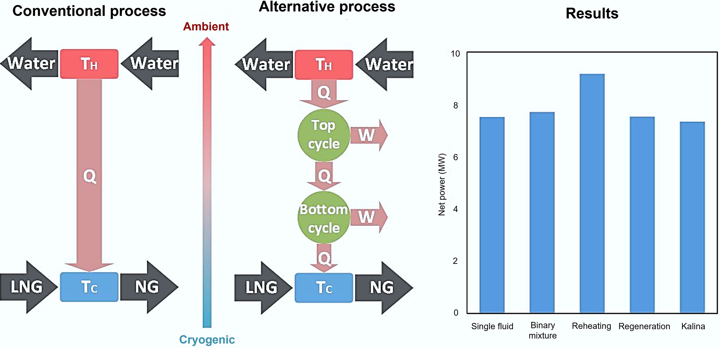
Liquefied natural gas (LNG) has become a critical energy carrier in today's global supply chain, enabling the transportation of natural gas in compact liquid form at approximately −162 °C and near atmospheric pressure. While converting natural gas from the gaseous to the liquid phase significantly enhances economic viability for long-distance transportation, the liquefaction process is energy-intensive and can account for more than 40% of the total cost in the LNG value chain[1,2]. Traditional liquefaction plants consume over 1,600 kJ·kg−1 during the liquefaction process, and although a considerable portion is dissipated as heat during refrigeration cycles, approximately 830 kJ·kg−1 is preserved as cold energy in LNG[3−6]. During the regasification process, where LNG is warmed and vaporized before entering downstream pipeline networks, this cold exergy is typically rejected to seawater or ambient air with minimal energy recovery[7,8]. Potential utilizations of this cold energy therefore present a substantial economic interest with the increasing global LNG consumption.
Research on cold energy power generation began in the 1970s when simple power cycles such as direct expansion (DEC), Rankine (RC), and Brayton cycle (BC) were first examined. More recent investigations have implemented multiple cycles and working fluids to attain higher thermal efficiencies[6]. Table 1 summarizes some representative LNG cold energy power generation designs with the corresponding working fluids, power outputs, and efficiencies reported in the literature.
Table 1. Summary of single fluid power generation designs
Ref. Power cycle (s) Working fluid (s) Heat source LNG flow (t·h−1) Power output (kW) Thermal efficiency (%) [9] RC + DEC Propane Seawater 1.62 59.79 N/A [10] RC Propane Seawater 108 2,200 10 [11] Three-stage RC Propane Seawater 3.6 106 12.5 [12] Two-stage RC Ethane, propane Seawater 3.6 96.1 11.1 [13] Two-stage RC Ethane, ethylene Seawater N/A N/A N/A [14] RC Ammonia-water Waste heat 8.87 389.4 25.9 [15] BC + RC + DEC Nitrogen (BC), ammonia-water (RC) Waste heat N/A N/A 53.1 [16] BC + DEC Helium Combustion 3.6 1,650 53.7a [17] BC + DEC Flue gas Combustion N/A N/A 55.5 [18] BC + RC + two-stage DEC Flue gas (BC), propane (RC) Combustion N/A N/A 33.9b a Exergy efficiency; b Thermal efficiency of the gas turbine in the Brayton cycle. Among various power cycle options, direct expansion cycles are the most straightforward to implement, but generally exhibit low efficiency because only the pressure-based exergy is utilized while substantial temperature-based exergy is wasted. Single direct expansion cycles are therefore rarely employed independently. Rankine cycles, in contrast, offer more effective frameworks resulting in higher net power output. Two-stage Rankine configurations, in particular, effectively enhance thermal efficiency while maintaining manageable system complexity, whereas adding further stages yields diminishing marginal improvements[11]. Brayton cycles, though thermodynamically efficient at high temperatures, are rarely applied when heat sources operate near ambient temperature, as limited temperature differentials between working fluids and LNG reduce net power output and may even require external power input[19].
One of the major challenges in designing power cycles for LNG cold energy recovery is the selection of the appropriate working fluids. While single fluids such as ethane (R170) or propane (R290) have been extensively studied and are relatively straightforward to implement, they tend to exhibit poor thermal matching with the non-isothermal LNG warming process, limiting the attainable exergy efficiency. Alternatively, binary or zeotropic mixtures exhibit a temperature glide during phase transition, facilitating improved thermal alignment with the LNG warming curve and thereby enhancing cycle performance. For instance, a recent study has reported that CO2-based binary mixtures can achieve higher efficiencies than pure CO2 in a single Rankine cycle configuration[20]. Similarly, a study on multi-stage cascade organic Rankine cycles using binary mixtures has achieved notable efficiency improvements[21]. Table 2 summarizes these two studies, highlighting the working fluid mixtures, operation temperature ranges, and thermodynamic performance.
Table 2. Summary of mixed working fluid power generation designs
Ref. Power cycle (s) Working fluid (s) Cold reservoir
(°C)Hot reservoir
(°C)LNG flow
(t·h−1)Power output
(kW)Thermal efficiency
(%)[20] RC CO2-based mixtures −55 to −30 25 3.6 13.5 N/A [21] Three-stage RC Mixtures of R14, methane to pentane −160 25 to 85 Varying 151.8 to 248.8a 18.6 to 27.1 a Per kg of LNG flow. While these studies highlight the potential of binary mixtures as working fluids, the number of detailed studies specifically optimizing mixed fluids for LNG cold energy recovery remains limited. The systematic evaluation of multi-stage cycle configurations with comprehensive working fluid combinations and full-range operation from LNG to ambient temperatures remains largely unaddressed.
In parallel, some recent works have also explored hybrid and multi-objective systems, leveraging LNG cold energy not only for power generation but also for secondary applications such as freshwater production or carbon capture, as summarized in Table 3.
Table 3. Summary of multi-objective power generation systems
Ref. Power cycle (s) Working fluid (s) Power output (kW) Thermal efficiency (%) Other applications [22] ORC CO2 31.2 5.0 Energy storage, chilled water, cold dry air [23] Three-stage ORC Ethane 11240 13.3a Desalination [24] ORC R1270 58870 63.8b Carbon capture ORC: Organic Rankine cycle; a Exergy efficiency; b System exergy efficiency. While multi-application designs demonstrate the versatility of LNG cold energy, such configurations are often region-specific. In this regard, the present study performs a comprehensive optimization of two-stage power cycles, evaluating both single and binary working fluid combinations simultaneously across various cycle configurations. Building upon and extending previous investigations[20,21], the present study integrates working fluid selection and cycle configuration analysis, analysing single and binary fluids across both stages and incorporating advanced modifications such as Kalina integration, regeneration, and reheating, to comprehensively evaluate the thermodynamic interactions in two-stage LNG cold energy recovery systems. In addition, the analysis underscores practical applicability by considering commercially available fluids, representative LNG regasification conditions, and practically feasible cycle configurations, facilitating the direct application of the optimization outcomes.
-
The power cycle design was developed through a systematic, multi-stage approach, beginning with a straightforward two-stage Rankine cycle as the baseline configuration. Building upon this reference case, alternative configurations were explored to enhance the utilization of LNG cooling capacity and improve overall cycle efficiency. In particular, a Kalina cycle configuration was implemented in the bottom stage, while the top stage was enhanced through regeneration and reheating modifications. This section describes the baseline design and its advanced configurations in sequence.
Two-stage Rankine cycle
-
The baseline configuration examined in this study is a two-stage Rankine cycle designed to recover the cold exergy during LNG regasification. As shown in Fig. 1, the system is composed of an upper and a lower cycle, each operating with an independent working fluid. In both stages, the working fluid follows a closed thermodynamic loop of evaporation, expansion, condensation, and pumping. Seawater serves as the heat source for the evaporation in the upper cycle, while LNG functions as the heat sink for the condensation in the lower cycle. An intermediate heat exchanger functions simultaneously as the condenser for the upper cycle and the evaporator for the lower cycle.
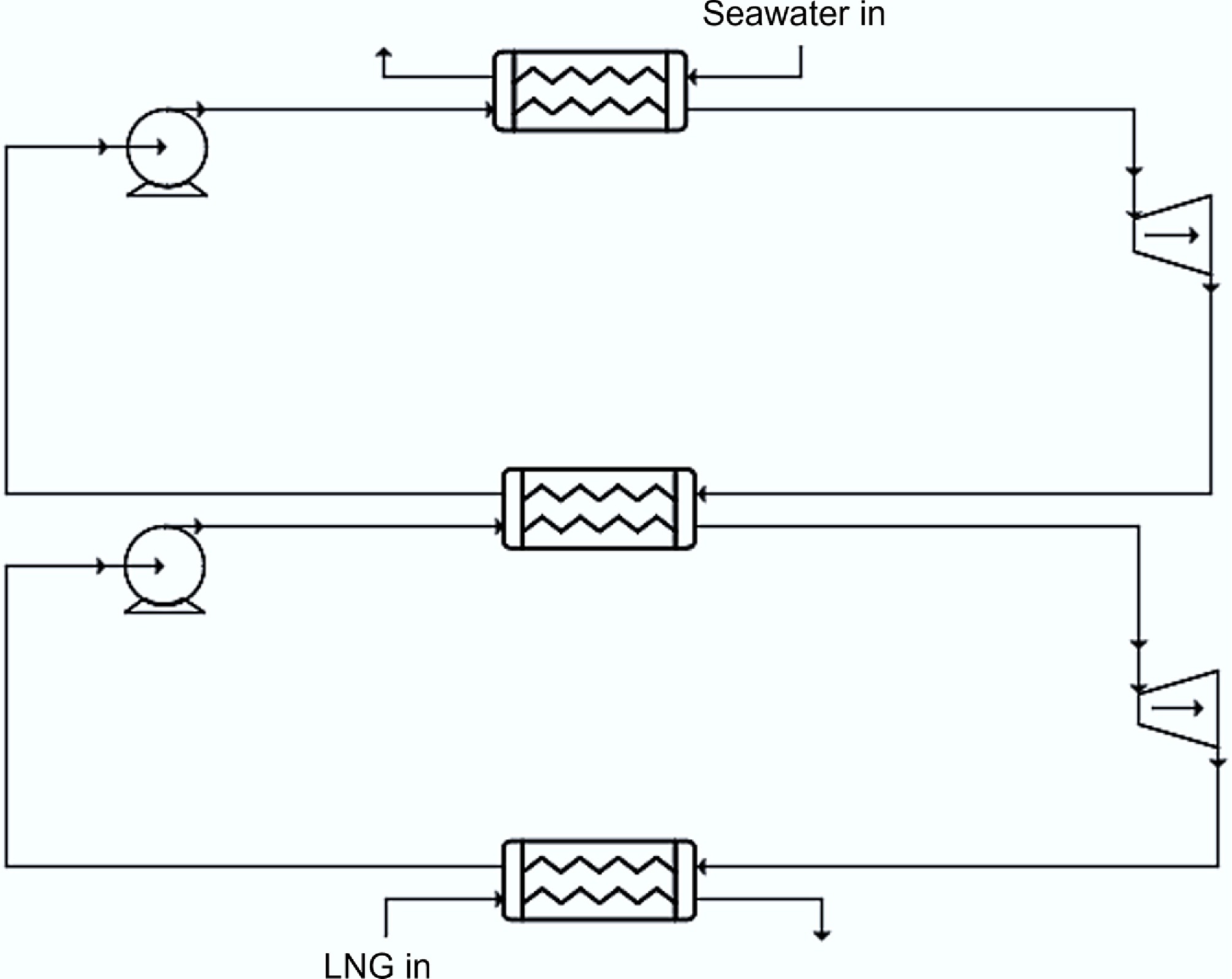
Figure 1.
A schematic of the two-stage Rankine cycle.
A single working fluid operating across the entire temperature span from LNG conditions to ambient temperature would experience substantial temperature mismatches with the heat source and sink, resulting in significant exergy destruction. The two-stage configuration reduces the operating temperature range for each cycle, allowing for improved temperature matching between the working fluids and their respective heat reservoirs.
In the simulation framework, the intermediate heat exchanger temperature is treated as an optimization variable, allowing the genetic algorithm to determine its optimal value. This study considers both single working fluids and working fluid mixtures for cycle optimization.
Cycle modifications
-
To enhance the performance of the baseline two-stage Rankine cycle, several advanced modifications were investigated. These enhancements aim to improve thermal matching between the working fluids and the LNG temperature profile, as well as to maximize the overall cycle efficiency. The following subsections detail the specific modifications implemented, including a Kalina cycle integration for the bottom stage, and regeneration and reheating enhancements for the top stage.
Kalina cycle
-
The Kalina cycle is a power cycle that employs a mixture of refrigerants as the working fluid to achieve variable boiling or condensation temperatures during the phase change processes. This characteristic enables superior temperature matching with non-isothermal heat sources or heat sinks, compared to the conventional single-component Rankine cycles that undergo isothermal phase transitions.
A unique feature of the Kalina cycle is the vapor-liquid separator, which splits the partially evaporated working fluid mixture into two streams: a vapor stream with a lower concentration of the heavy component, and a liquid stream with a higher concentration of the same component. The vapor stream is subsequently expanded through the turbine for power generation, while the liquid stream undergoes Joule-Thomson expansion and is then mixed with the turbine exhaust to enhance heat recovery and cycle efficiency. Although these processes are inherently irreversible and generate entropy, the overall cycle performance can be improved by enabling better temperature matching within the system.
As illustrated in Fig. 2, the Kalina cycle retains the essential closed-loop framework of a Rankine cycle while incorporating a separator alongside the standard evaporator, turbine, condenser, and pump components. In contrast to the traditional Kalina cycles that utilize ammonia-water solution as the working fluid, this research investigates mixtures of organic refrigerants to optimize temperature matching with the non-isothermal LNG warming curve.
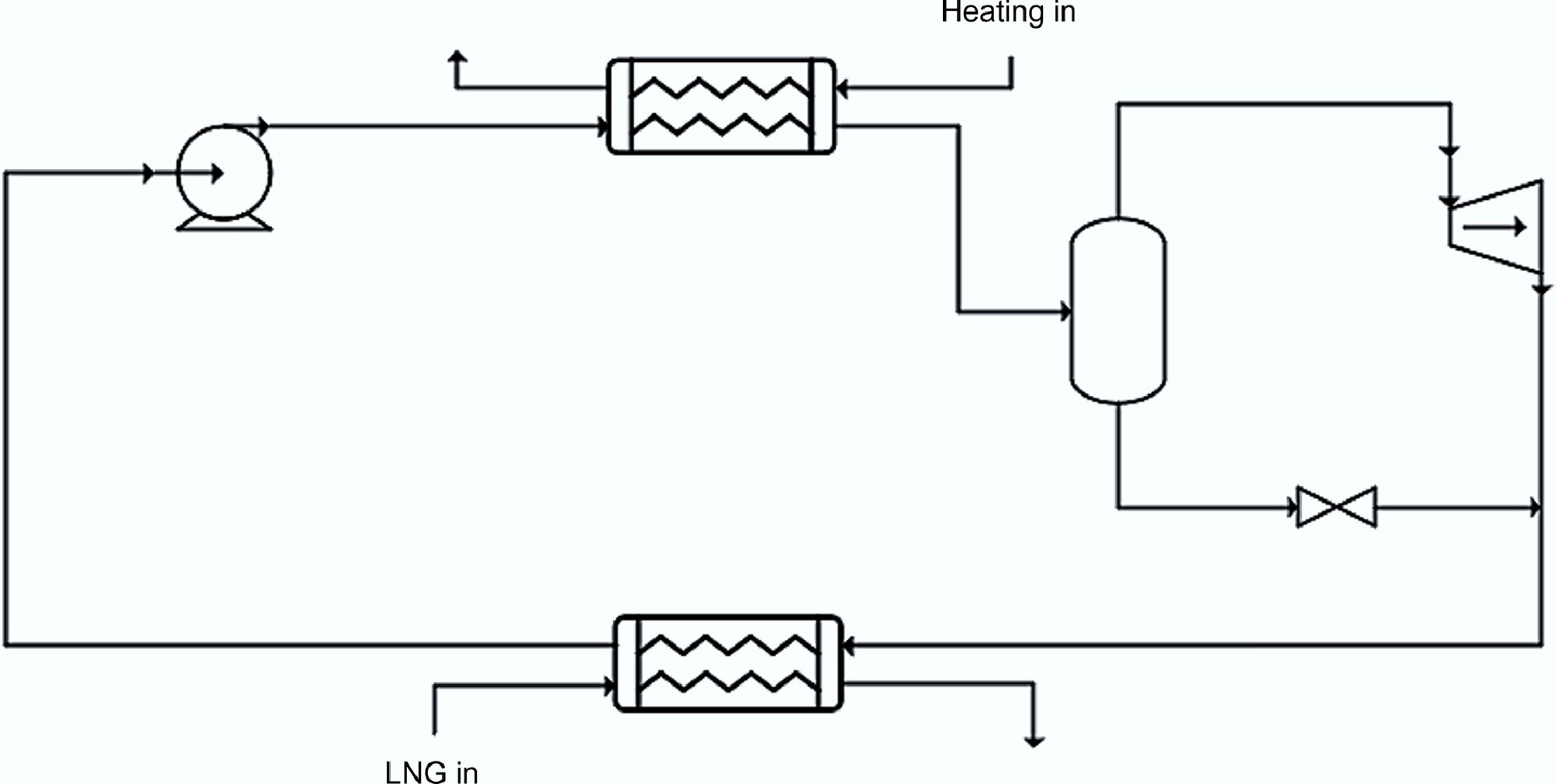
Figure 2.
A schematic of a basic Kalina cycle.
Regeneration
-
Regeneration is a thermodynamic enhancement for the Rankine cycle that utilizes turbine exhaust energy to preheat the high-pressure liquid working fluid prior to evaporation. As illustrated in Fig. 3, a heat exchanger, commonly known as the regenerator, is positioned to transfer heat from the low-pressure turbine exhaust to the high-pressure liquid exiting the pump. This internal heat recovery process reduces external heat input requirements by capturing residual thermal energy that would otherwise be rejected to the heat sink, thereby improving overall cycle thermal efficiency. The preheating effect reduces the temperature differential between the heat source and working fluid during evaporation, and hence minimizes exergy destruction in the heat transfer process in the evaporator. The extent of performance improvement depends on the regenerator effectiveness, which represents the fraction of available exhaust heat that is successfully transferred to the liquid stream.
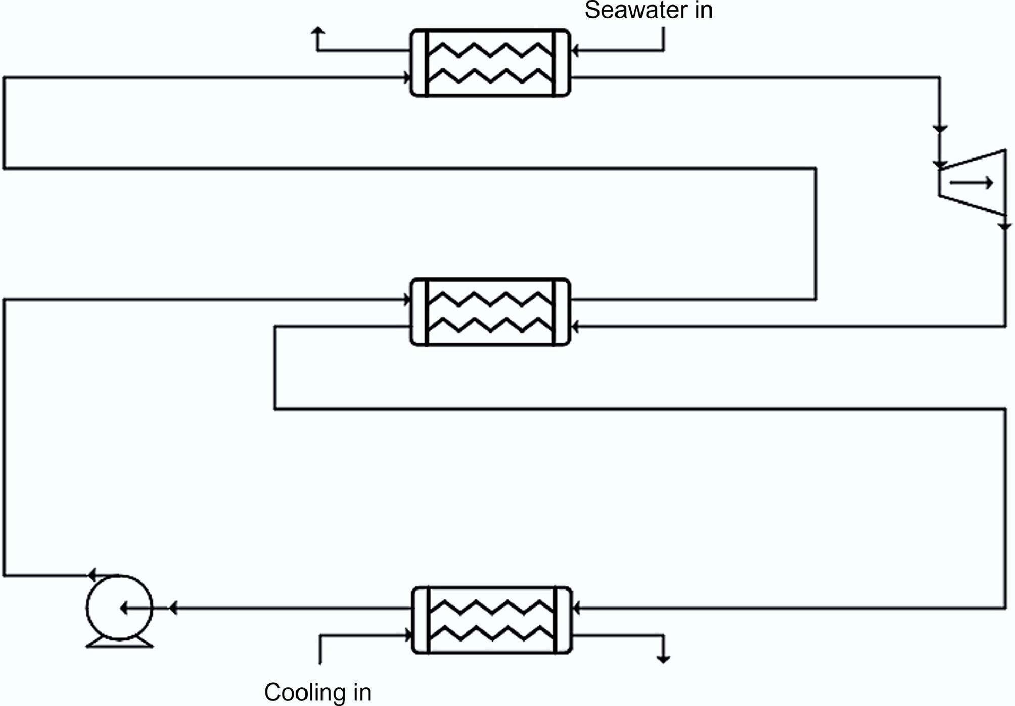
Figure 3.
A schematic of the basic regeneration configuration.
While regeneration provides efficiency gains, it also introduces additional hardware requirements and pressure drop to the working fluid. The net benefit of regeneration must therefore be evaluated considering both thermodynamic performance improvements and practical implementation factors in the overall system design.
Reheating
-
Reheating is another thermodynamic modification to the Rankine cycle where partially expanded working fluid is extracted from an intermediate turbine stage, returned to the heat source for additional heating, and subsequently expanded through a second turbine stage to complete the expansion process. As illustrated in Fig. 4, this dual-turbine configuration enables controlled expansion across multiple pressure stages while maintaining elevated working fluid temperatures. The primary thermodynamic benefit of reheating is the increase in average temperature of the heat addition processes, which directly improves the thermal efficiency of the cycle. Additionally, reheating significantly reduces moisture content in the working fluid during the final expansion stages, preventing excessive moisture formation that can cause mechanical damage to turbine components.
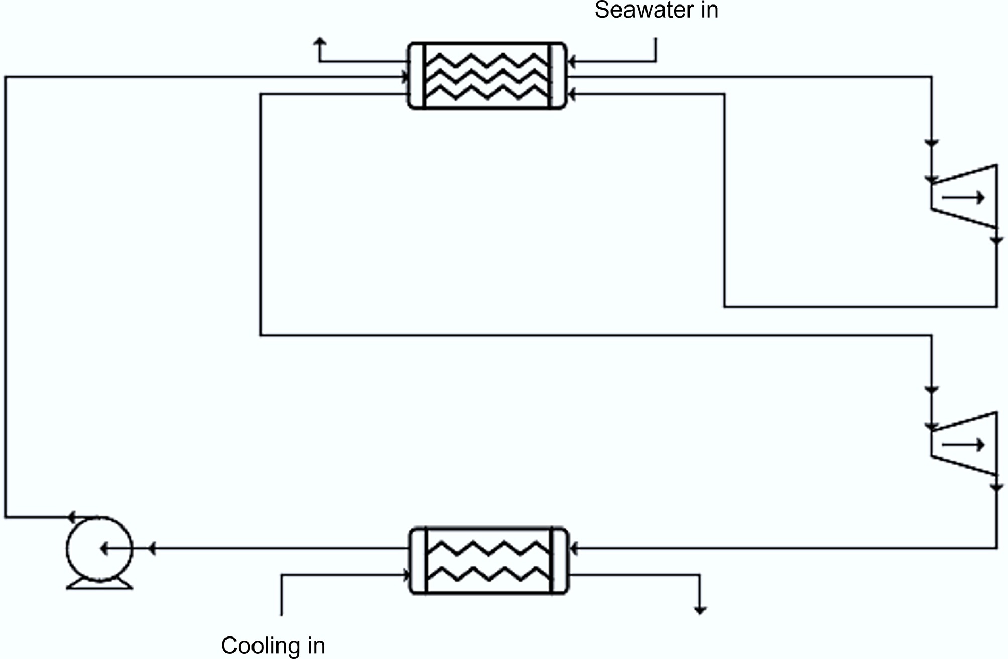
Figure 4.
Schematic of a basic reheating configuration.
Although reheating provides substantial thermal efficiency improvements compared to non-reheat configurations, this enhancement also comes at the cost of increased system complexity and additional heat exchanger requirements. The optimal reheat pressure represents a critical design parameter that balances efficiency gains against practical implementation considerations, including additional pressure drop and the potential for superheated exhaust conditions that increase thermal load in the condenser without contributing useful work.
Integrated configurations
-
Building upon the individual cycle modifications described previously, four integrated configurations were developed to maximize the thermodynamic potential of the two-stage system. These configurations systematically combine either a Rankine or a Kalina cycle for the bottom stage, with regeneration or reheating enhancements in the top stage to achieve optimal performance across the wide temperature range.
The first two configurations employ a conventional Rankine cycle for the bottom stage while incorporating top-stage enhancements. As shown in Fig. 5a, the Rankine-regeneration configuration employs a regenerator for the internal heat recovery in the top cycle to improve thermal efficiency through reduced external heat input. The Rankine-reheating configuration, illustrated in Fig. 5b, utilizes a dual-stage expansion in the top cycle to increase the average temperature in the heat addition processes, while also controlling the moisture content.
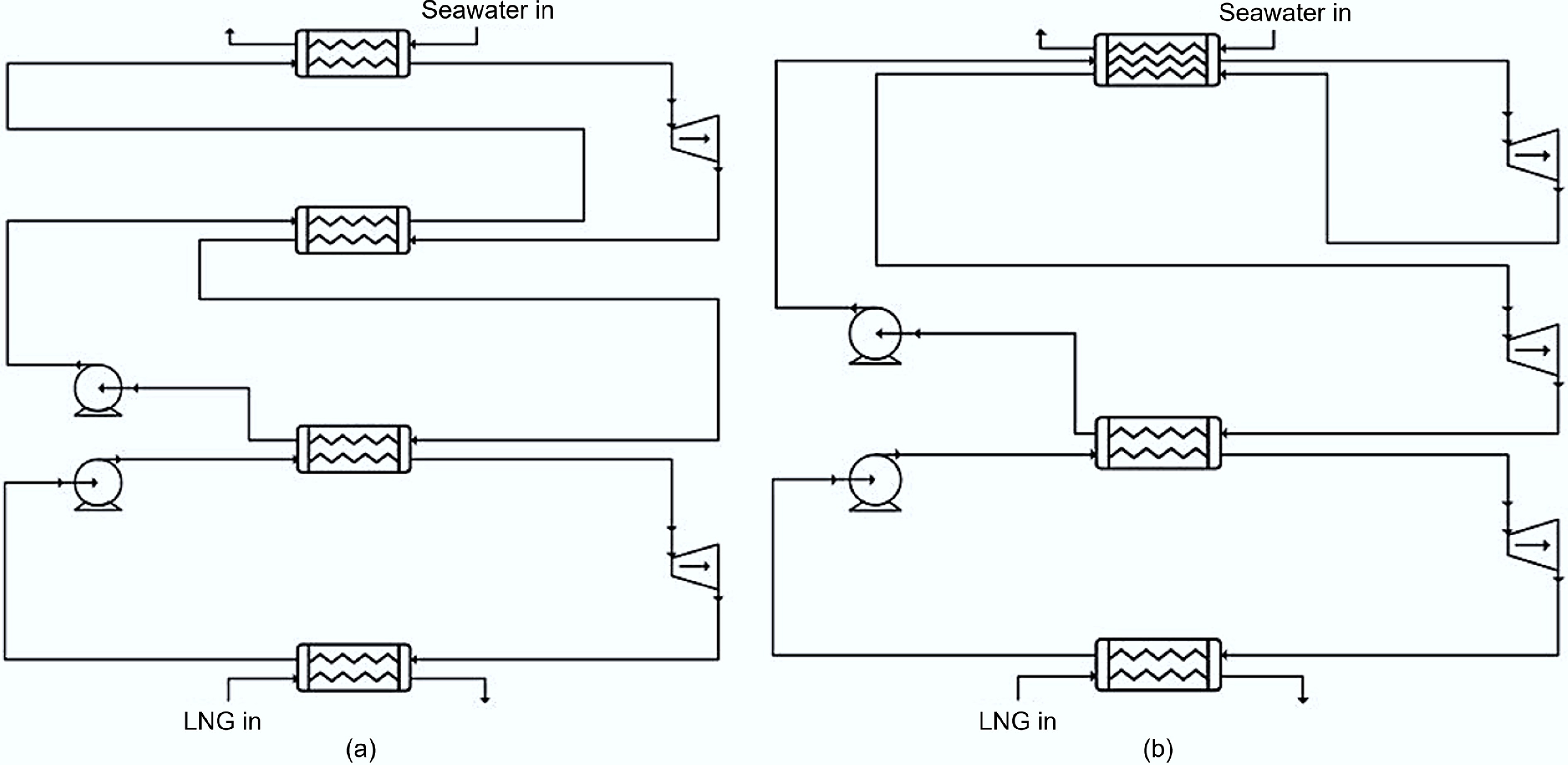
Figure 5.
Schematic of (a) Rankine-regeneration process configuration, and (b) Rankine-reheating process configuration.
The remaining two configurations employ the Kalina cycle for the bottom stage to enhance temperature matching between the working fluid condensation and the LNG warming profile. Figure 6a presents the Kalina-regeneration configuration, which combines the variable-temperature evaporation characteristics of the mixed working fluid in the bottom stage with a regenerator in the top stage for heat recovery. Figure 6b depicts a Kalina-reheating configuration, which incorporates a Kalina cycle in the bottom and a dual-stage expansion in the top cycle, representing the most complex configuration examined in this study. The Kalina cycle is positioned as the bottom cycle instead of the top cycle because it is well suited for low-temperature applications, being widely applied both in low-grade heat systems (around 200 °C) and in cryogenic LNG cold energy recovery[25,26].
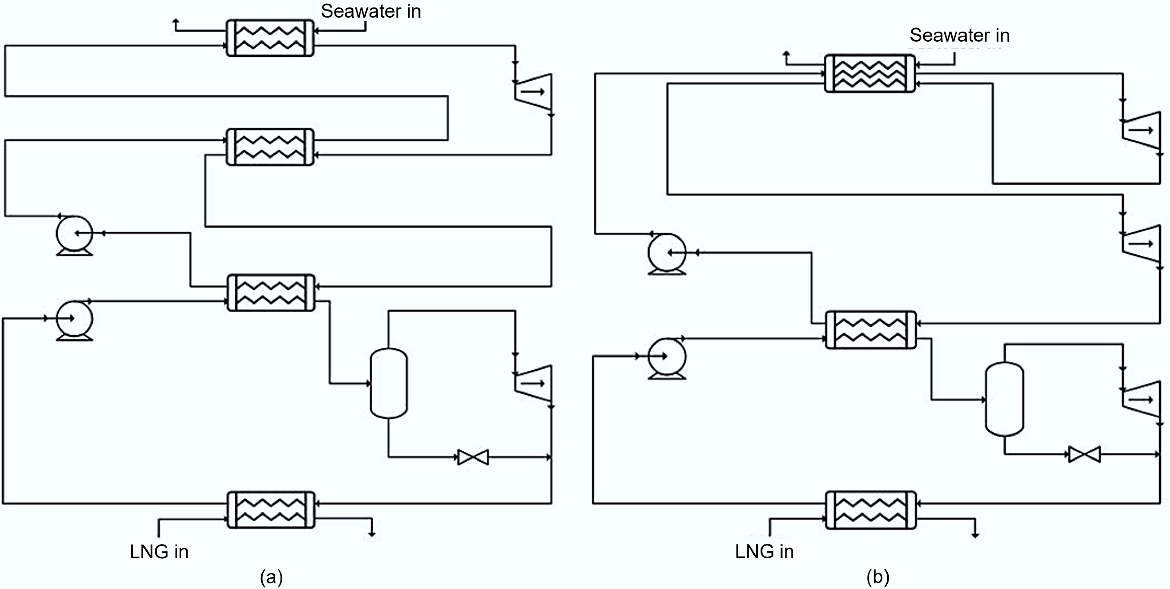
Figure 6.
Schematic of (a) Kalina-regeneration process configuration, and (b) Kalina-reheating process configuration.
These integrated designs enable a comprehensive evaluation of individual and synergistic effects of cycle modifications, providing insights into optimal configuration selection for LNG cold energy recovery applications.
-
This section presents the systematic methodology for fluid selection, thermodynamic modelling, and process optimizations. Implementation details include working fluid selection criteria, simulation boundary conditions and assumptions, and genetic algorithm parameter settings for the automated optimization process. This systematic approach ensures a comprehensive evaluation of all design variants while maintaining consistency across performance comparisons.
In this study, the terms performance and overall performance are used interchangeably to denote the net power output of the integrated power cycle system. The net power output is defined as the total power generated by all turbines minus the total power consumption of all pumps across both the top and bottom cycles. When the performance of an individual cycle stage is discussed, it refers to the net power contribution of that specific stage, defined as the turbine power output minus the associated pump power input within that stage.
Working fluid selections
-
The selection of working fluids represented a critical factor in power cycle performance. The selection process involves establishing thermodynamic and practical criteria for single fluid candidates, followed by a systematic approach for identifying promising binary mixtures based on single fluid screening results. In this context, the study has examined commonly used refrigerants and subsequently generated binary mixtures from the most promising single fluid candidates, maintaining feasibility and alignment with commercially available options.
Selection criteria
-
Potential working fluid candidates for low-temperature power cycles are summarized in Table 4. Several thermodynamic criteria must be satisfied for effective operations in Rankine cycles. Firstly, to prevent vacuum conditions within the system, the saturation pressure of the working fluid at the lowest operating temperature should exceed the atmospheric pressure. Secondly, effective turbine operation requires adequate pressure differences between turbine inlet and outlet. Based on the highest operating temperatures of approximately 0 and −30 °C for the upper and lower cycles, respectively, working fluids must exhibit saturation pressures exceeding 200 kPa at these temperatures to maintain sufficient pressure differentials above a threshold of 100 kPa adopted in this study. Thirdly, the critical temperature and pressure should exceed the maximum operating conditions to maintain a subcritical operation throughout the cycle. Finally, to avoid solidification, the triple point conditions of the working fluids must remain below the minimum system operating temperatures or pressures. Specific working fluid candidates meeting these criteria are evaluated and presented in the following results section.
Table 4. Working fluid candidates for low-temperature power cycle
Working fluid Chemical name Chemical
formulaTC
(°C)PC
(kPa)TTP
(°C)PTP
(kPa)TS @
100 kPa (°C)PS @
−70 °C (kPa)PS @
−30 °C (kPa)PS @
0 °C (kPa)Category R1150 Ethylene C2H4 9.2 5,032 −169.2 0.12 –104.3 517.6 1,062 4,109 Wet R116 Hexafluoroethane C2F6 19.9 3,060 −100 26.1 –79 157.9 377.3 1,872 Dry R23 Fluoroform CHF3 25.9 4,836 −155.1 0.058 –82.2 193.3 479.5 2,525 Dry R170 Ethane C2H6 32.3 4,884 −182.9 0.0011 –89 250.9 553 2,401 Wet R125 Pentafluoroethane C2HF5 66 3,620 −100.6 2.9 –48.4 30.6 92.4 668 Dry R143a 1,1,1-Trifluoroethane C2H3F3 72.7 3,764 −111.8 1.1 –47.4 29.8 88.3 620 Dry R32 Difluoromethane CH2F2 78.5 5,820 −136.8 0.048 –51.9 36 110.5 821 Wet R290 Propane C3H8 96.7 4,242 −187.6 1.7e–7 –42.7 25.3 71.9 476 Wet R1270 Propylene C3H6 92.4 4,664 −185.2 7.5e–7 –48.3 33.4 92.6 586 Wet R134a 1,1,1,2-Tetrafluoroethane C2H2F4 101 4,056 −103.3 0.39 –26.4 8.2 29.8 292 Dry R14 Tetrafluoromethane CF4 −45.7 3,745 −153.2 11.3 –128.3 1,739 3,302 N/A Dry R152a 1,1-Difluoroethane C2H4F2 113.9 4,444 −118.6 0.064 –24.8 8.2 28.7 266 Dry RC318 Perfluorocyclobutane C4F8 118.8 2,330 −39.8 19.5 –3.3 N/A 10.8 113 Dry R600a Isobutane C4H10-2 134.8 3,655 −159.4 2.3e–5 –12.4 5.1 17.5 158 Dry R600 n-Butane C4H10-1 152 3,796 −138.3 6.7e–4 –0.86 2.6 9.7 103 Dry R601a Isopentane C5H12-2 187.2 3,334 −160.5 9e–7 27.5 0.53 2.4 35 Dry R601 n-Pentane C5H12-1 196.4 3,375 −129.7 7.8e–5 35.9 0.29 1.4 24 Dry R744 Carbon Dioxide CO2 31 7,384 −56.6 517.9 N/A N/A 677 3,474 Isentropic R717 Ammonia NH3 132.3 11,310 −77.7 6.1 –33.4 10.7 40.2 427 Wet TC: Critical temperature; PC: Critical pressure; TTP: Triple point temperature; PTP: Triple point pressure; TS: Saturation temperature; PS: Saturation pressure. Mixed working fluid
-
A major challenge in the selection of working fluids for power cycles utilizing LNG as the cold reservoir lies in achieving effective thermal matching with the non-isothermal warming profile of the LNG. In a conventional single-component Rankine cycle, condensation of the working fluid occurs isothermally, which leads to substantial temperature mismatches with the non-isothermal warming curve of LNG. In this regard, mixed working fluids are investigated due to their non-isothermal condensation characteristics across a temperature range. This property enables an improved thermal matching with the LNG warming curve. While multi-component mixtures are possible, this study focuses on binary mixtures for computational simplicity.
The selection methodology focuses on binary combinations of the best-performing single working fluids from the previous section, with the assumption that effective individual components may perform well when combined. This approach reduces the computational costs of evaluating all possible fluid combinations while maintaining systematic selection criteria. The compositions of the components are treated as optimization variables within the genetic algorithm framework, with the specific mixture candidates detailed in the results and discussion section.
Simulation parameters
-
The LNG conditions and the simulation parameters are outlined in Table 5. All simulations were performed using the Peng–Robinson equation of state, which is commonly used for fluorinated refrigerants and provides reliable predictions of phase equilibrium at cryogenic temperatures[27,28].
Table 5. LNG conditions and simulation parameters
Parameter Value LNG compositions (mol%): Methane 85 Ethane 10 Propane 2.5 n-butane 2.5 LNG inlet temperature (°C) −130 LNG outlet temperature (°C) −95 LNG pressure (kPa) 1,000 LNG mass flow rate (kg·s−1) 60 Pump/turbine adiabatic efficiency (%) 75 Pressure drop in the heat exchanger (kPa) 10 Minimum pinch point in heat exchangers (°C) 5 Genetic algorithm settings
-
A genetic algorithm is employed in this study to optimize the thermodynamic performance of the proposed power cycle configurations. The algorithm was implemented in Python, providing an automated interface with Aspen HYSYS simulation software for systematic parameter evaluation. Optimization results are exported to an Excel sheet and then further analyzed. The optimization workflow structure is depicted in Fig. 7.
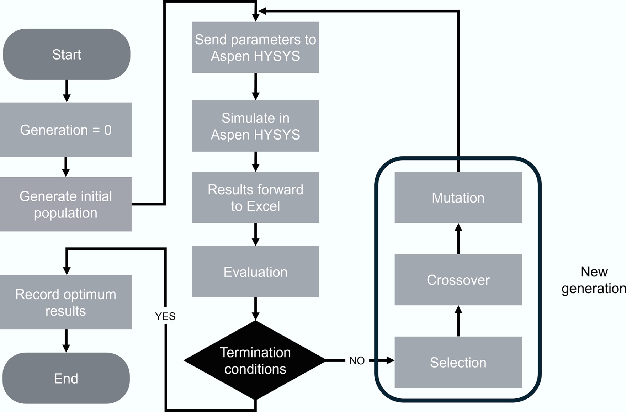
Figure 7.
The genetic algorithm flowsheet.
The capability of the genetic algorithm to identify global optima facilitates a comprehensive exploration of the design space. Consequently, broad parameter ranges are assigned to each design variable to ensure thorough investigation of the potential configuration combinations and identification of the optimal operating conditions. The specific parameter ranges and genetic algorithm settings for each cycle configuration are presented in Tables 6 and 7. In this study, the genetic algorithm is executed for a fixed number of generations, which constitutes the termination condition for all optimization cases. The optimization problem is formulated as a single-objective problem, with the objective of maximizing the thermodynamic performance of the proposed power cycle and working fluid combinations. Specifically, the net power output of the integrated cycle system is adopted as the optimization objective, enabling a consistent and direct comparison of performance across different configurations.
Table 6. Parameter value ranges
Parameters Range Top cycle evaporation pressure 200 kPa to PS @ 0 °C Top cycle condensation pressure 100 kPa to PS @ 0 °C Bottom cycle evaporation pressure 200 kPa to PS @ 30 °C Bottom cycle condensation pressure 100 kPa to PS @ 30 °C Bottom cycle evaporation temperature –70 to –30 °C Additional parameters for mixed fluid Top mixture composition (component 1) 0.1 to 0.9 Bottom mixture composition (component 2) 0.1 to 0.9 Additional parameters for reheating configuration Top cycle evaporation pressure 2 200 kPa to PS @ 0 °C Additional parameters for Kalina configuration Separator ratio* 0.1 to 0.9 * Vapor fraction of the separator feed on a molar basis. Table 7. Genetic algorithm settings
Algorithm settings Value Total generations 50/100* Populations per generation 100/200* Mutation probability 0.2 * For integrated configurations with Kalina, reheating, and regeneration. For configurations incorporating additional cycle features such as Kalina bottoming, reheating, and regeneration, a larger population size and number of generations were adopted to account for the increased number of decision variables and the resulting higher-dimensional, more complex optimization landscape, thereby improving convergence robustness.
The maximum evaporation and condensation pressures correspond to the saturation pressures of the respective working fluids at 0 and –30 °C for the top and bottom cycle, respectively. Pressures above the saturation pressures would result in subcooled liquid, which prevents proper phase change and power extraction from the turbines. To ensure effective power generation and prevent operation below atmospheric pressure, the lower limits are set at 200 and 100 kPa for the evaporation and condensation pressures of each cycle, respectively. A constraint is imposed within the algorithm to maintain evaporation pressures above the corresponding condensation pressures. Furthermore, a wide range from 0.1 to 0.9 is specified for component compositions and separator ratios to enable extensive parametric exploration.
-
This section presents the optimization results and performance analysis for the proposed LNG cold energy recovery systems. The evaluation examines single working fluid performance, mixed working fluid performance, and advanced cycle configurations incorporating Kalina cycles with regeneration and reheating enhancements.
Single working fluid
-
Based on the selection criteria established in the previous section, six working fluid candidates were identified for the upper cycle: ethylene (R1150), hexafluoroethane (R116), fluoroform (R23), ethane (R170), difluoromethane (R32), and carbon dioxide (R744). For the lower cycle, five candidates met the thermodynamic requirements: ethylene (R1150), hexafluoroethane (R116), fluoroform (R23), ethane (R170), and tetrafluoromethane (R14). These working fluid selections resulted in 30 possible combinations, as illustrated in Table 8.
Table 8. Combinations of single working fluid
Bottom cycle
working fluidTop cycle working fluid R1150 R116 R23 R170 R32 R744 R1150 1 2 3 4 5 6 R116 7 8 9 10 11 12 R23 13 14 15 16 17 18 R170 19 20 21 22 23 24 R14 25 26 27 28 29 30 The optimization results are presented in Fig. 8, where combinations are grouped by upper cycle working fluid, with different colored bars representing the corresponding lower cycle working fluid candidates. It was obvious that combinations utilizing R116 as the upper cycle working fluid consistently achieved superior performance compared to other candidates. For the lower cycle, both R1150 and R170 demonstrate significantly higher efficiency than the remaining working fluids. The optimal combination employs R116 for the upper cycle and R170 for the lower cycle, achieving a maximum net power output of 7.5 MW.
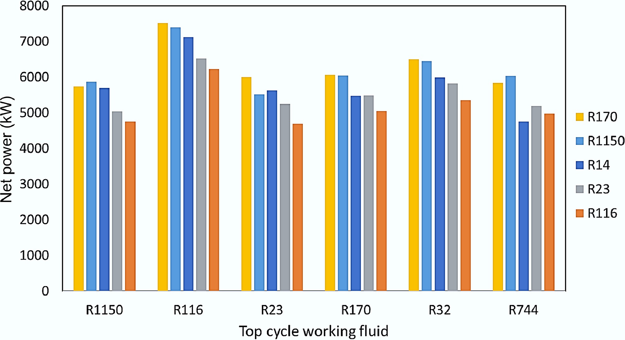
Figure 8.
Net power output for single working fluid combinations.
The optimization results reveal that working fluid selection for the upper cycle is relatively straightforward, with R116 consistently delivering superior performance across all combinations. A key characteristic of R116 is its behavior as a dry working fluid, remaining in the vapor phase after turbine expansion rather than forming a two-phase mixture. While this property poses challenges in single-stage power cycles due to the increased condenser thermal load from latent heat removal, it provides significant benefits in two-stage configurations where the rejected heat serves as the heat source for the lower cycle. Furthermore, R116 exhibits a non-isothermal cooling profile during heat rejection, transitioning from superheated vapor through two-phase conditions to a subcooled liquid, which aligns with the heating profile of the bottom cycle. Additionally, R116 exhibits a relatively high evaporation temperature of approximately –20 °C under optimal conditions, which is close to ambient conditions and significantly reduces the entropy generation during the heat transfer process. Table 9 presents the performance breakdown for some of the best and worst-performing combinations.
Table 9. Performance comparison of selected single working fluid combinations
Top cycle Bottom cycle Power
(MW)Top cycle power
(MW)Bottom cycle power
(MW)Thermal
efficiency
(%)2nd law
efficiency
(%)R116 R170 7.5 4.4 3.2 24.1 52.8 R116 R1150 7.4 4.4 3.0 23.8 52.1 R116 R14 7.1 4.0 3.2 23.1 50.7 R1150 R14 5.7 1.9 3.8 19.4 42.5 R1150 R116 4.8 2.6 2.2 16.7 36.6 R23 R116 4.7 2.5 2.2 16.5 36.2 The bottom cycle working fluid selection presents greater complexity. While R14 demonstrates the highest individual bottom cycle performance due to its lowest saturation temperature (–128.3 °C) providing optimal thermal matching with LNG, combinations featuring R14 consistently underperform due to poor thermodynamic compatibility with the upper cycle candidates. This mismatch substantially compromises top cycle power generation and results in mediocre overall performance, highlighting the importance of a comprehensive system optimization rather than individual component performance.
The significance of proper integration of working fluids is further illustrated by R116's poor performance as a bottom cycle working fluid. Despite its superior performance as the top cycle working fluid, R116 produces the worst overall results when positioned in the bottom cycle, where its dry fluid characteristics result in extra heat rejection to the LNG without generating additional useful work.
These findings establish R116 as the optimal upper cycle working fluid for LNG cold energy recovery applications, while highlighting bottom cycle working fluid selection as the primary optimization challenge. The superior performance of R116–R170 combinations (7.5 MW) provides a strong baseline for evaluating mixed working fluid enhancements in the following section.
Mixed working fluid
-
Mixed working fluids offer the advantage of non-isothermal phase change, evaporating and condensing over a range of temperatures as illustrated in the Temperature-composition (Txy) diagram in Fig. 9. In contrast to single fluids with fixed evaporation points, a binary mixture exhibits phase change across a temperature range confined by the boiling points of the two components. This characteristic enables improved thermal matching with the temperature-varying LNG warming curve.
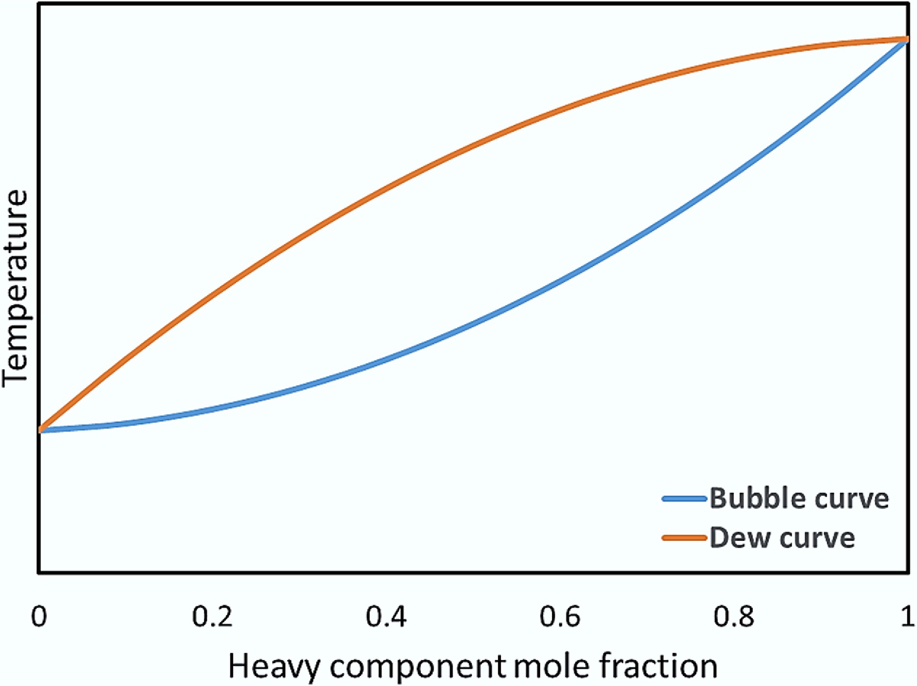
Figure 9.
Txy diagram of a binary mixture.
Mixed working fluid candidates were selected based on this thermodynamic principle. For the bottom cycle with the LNG temperature ranging from –130 to –95 °C, effective thermal matching requires a mixture to evaporate close to this temperature range. Low-temperature components with saturation temperatures slightly above –130 °C were paired with higher-temperature components having saturation temperatures above –95 °C. Based on this strategy, the bottom cycle mixtures combined low-temperature fluids R14 (–128.3 °C) and R1150 (–104.3 °C) with higher-temperature fluids R170 (–89.0 °C), R23 (–82.2 °C), and R116 (–79.0 °C). Similarly, as the cold reservoir for the upper cycle operated between approximately –70 and –30 °C, mixtures were formed using low-temperature components R116 (–79.0 °C) and R23 (–82.2 °C) with higher-temperature components R125 (–48.4 °C), R143a (–47.4 °C), and R1270 (–48.3 °C). It is assumed that the working fluids can form a miscible binary mixture. Single working fluids R116 and R170 are also included in the top and bottom cycle optimizations as a comparison, as they are the best-performing single working fluids in the previous section. These working fluid selections result in 49 possible combinations, as illustrated in Table 10. The mixture compositions were treated as optimization variables within the genetic algorithm framework, allowing determination of optimal component fractions for each binary combination. The results in this subsection pertain to the Rankine-Rankine configuration.
Table 10. Combinations of mixtures of working fluids
Bottom cycle
working fluidTop cycle working fluid R116–
R125R116–
R143aR116–
R1270R23–
R125R23–
R143aR23–
R1270R116 R14–R170 1 2 3 4 5 6 7 R14–R23 8 9 10 11 12 13 14 R14–R116 15 16 17 18 19 20 21 R1150–R170 22 23 24 25 26 27 28 R1150–R23 29 30 31 32 33 34 35 R1150–R116 36 37 38 39 40 41 42 R170 43 44 45 46 47 48 49 The optimization results are presented in Fig. 10, where combinations are grouped by upper cycle working fluid, with different colored bars representing the corresponding lower cycle working fluid candidates. While the average net power output for most combinations is improved compared to the single working fluid combinations, combinations utilizing R116 as the upper cycle working fluid remain the best performing ones. For the lower cycle working fluid, different candidates show similar results, with R1150–R23 mixture yielding the best result. The optimum conditions are achieved with 75 mol% of R1150. Under the optimum conditions, the combination generates 7.7 MW of power, which is approximately 2.6% higher than that of the single working fluid counterpart.
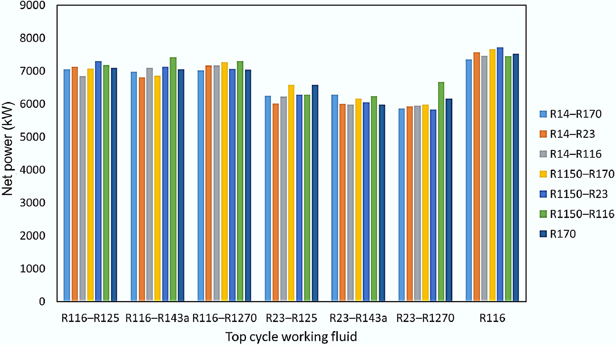
Figure 10.
Net power output for mixed working fluids combinations.
It is obvious that combinations utilizing R116 as the top cycle working fluid remain the best performing combinations. In fact, combinations where the top cycle generates the maximum power also demonstrate the best overall performance. In contrast, combinations exhibiting the highest power output from the bottom cycles tend to achieve inferior overall performance, as illustrated in Table 11. While these combinations yield higher net power outputs for both cycles compared to their single fluid counterparts, their overall performance is still considerably inferior to those with an optimally performing top cycle. This indicates that even when binary mixtures are employed as working fluids, the thermal matching in the bottom cycle, and hence its performance, remains mediocre. This demonstrates the necessity of optimizing the entire system rather than focusing on a single stage, since a binary mixture may achieve improved thermal matching with LNG in the bottom cycle while still leaving a significant temperature mismatch with the top cycle.
Table 11. Performance comparison of selected mixed working fluid combinations
Top cycle Bottom cycle Power (MW) Top cycle power (MW) Bottom cycle power (MW) Thermal efficiency (%) 2nd law efficiency (%) R116 R1150–R23 7.7 4.3 3.4 24.6 53.8 R116 R14–R116 7.4 4.7 2.8 24.0 52.5 R116–R143a R14–R23 6.8 2.5 4.3 22.3 48.9 R23–R143a R1150–R23 6.0 1.9 4.1 20.3 44.5 R23–R143a R14–R23 6.0 3.9 2.1 20.2 44.3 A distinctive feature of the mixed working fluid optimization is that the component fraction of the binary mixtures is treated as a variable within the optimization algorithm. This introduces additional degrees of freedom to the system and allows the algorithm to identify the optimal operating conditions for each combination through adjustment of the mixture composition. Consequently, mixed working fluid candidates generally show better average performance than single fluid candidates. For instance, all combinations employing R116 as the top cycle working fluid and a mixed working fluid in the bottom cycle perform similarly well, within roughly 5% of the best performing candidate, as shown in Fig. 10. In contrast, single fluid combinations exhibit more dispersal performance, even when the top cycle working fluid is identical.
On the other hand, mixed fluid combinations exhibit more irregular results with less clear trends. This is because binary mixtures with nominally identical components but differing composition ratios exhibit fundamentally distinct thermodynamic behaviour, effectively functioning as different working fluids. For example, employing R1150–R23 as the bottom cycle working fluid yields the highest net power output when paired with R116 as the top cycle working fluid, yet delivers an inferior result when paired with R23–R143a as the top cycle working fluid. In these two cases, the composition of the R1150–R23 mixture may not be identical, meaning they are effectively different working fluids thermodynamically. Similarly, employing the same binary mixture, R14–R23, as the bottom cycle working fluid results in both the best and worst bottom cycle performance when paired with different top cycle working fluids. As a result, each mixed fluid combination behaves as a distinct candidate, and direct comparisons between mixtures are not meaningful, even when one of the components remains identical. This variability explains the irregular trends observed in the optimization landscape for mixed working fluids.
Advanced configurations
-
Building upon insights from single and mixed working fluid evaluations, the four advanced cycle configurations detailed in the integrated configurations section were systematically simulated and optimized. The integrated configurations, summarized in Table 12, with the corresponding schematic diagrams presented in Figs 5 and 6, combine Rankine and Kalina cycles, regeneration, and reheating modifications in various arrangements.
Table 12. Advanced configurations
Bottom cycle configuration Top cycle configuration Regeneration Rankine cycle Reheating Rankine cycle Rankine cycle Configuration 1 Configuration 2 Kalina cycle Configuration 3 Configuration 4 To minimize the computational demand, the optimization process considered only the best performing working fluid candidates identified from the preceding analysis, as listed in Table 13, instead of all possible combinations. It is important to note that a single working fluid cannot operate within a Kalina cycle because it does not generate the necessary rich and lean solutions from the separator. Therefore, for consistency in optimization and comparison, R170 was excluded as a bottom cycle candidate, despite its strong performance as a single working fluid. Each working fluid combination was systematically evaluated across all four advanced configurations to identify the optimal pairing between cycle type and working fluid.
Table 13. Working fluid candidates for advanced cycle configurations
Bottom cycle working fluid Top cycle working fluid R116 R14–R170 1 R14–R23 2 R14–R116 3 R1150–R170 4 R1150–R23 5 R1150–R116 6 The optimization results are presented in Fig. 11, where combinations are grouped by different cycle configurations, with the different colored bars representing the corresponding lower cycle working fluid candidates. The results reveal that both Kalina cycle integration and regeneration modifications do not enhance the performance, while the reheating modifications achieve substantial performance improvements across all working fluid combinations. The optimal configuration employs an R1150–R170 mixture as the bottom cycle working fluid in a Rankine–reheating configuration, generating 9.2 MW net power output under optimized conditions. This represents an approximately 22% and 19% improvement over the best-performing single and mixed working fluid combinations.
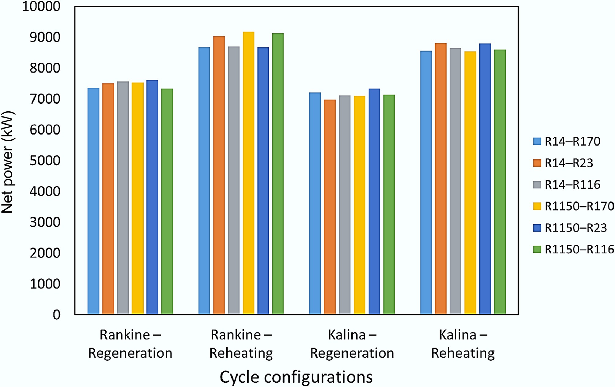
Figure 11.
Net power output for advanced cycle configurations.
Table 14 presents the detailed optimal operating conditions for the same working fluid combination across different configurations. The top cycle employs R116 as the working fluid, paired with R1150–R170 as the bottom cycle working fluids (pure R170 for the single-fluid configuration). The reheating configuration demonstrates superior performance in both cycles, generating substantially higher power outputs compared to alternative configurations. This improvement primarily results from the significantly larger pressure gradient across the turbine. In the reheating configuration, R116 can be pressurised to 1,830 kPa prior to expansion, while single-stage expansion configurations reach only 870–1,030 kPa. From a thermodynamic perspective, single-stage expansion of dry working fluids like R116 across large pressure ratios results in excessively low turbine exhaust temperatures, as the fluid remains in the superheated vapor phase throughout expansion and cools substantially through isentropic work extraction. This limits the available heat transfer to the bottom cycle and suppresses the overall performance. The two-stage expansion architecture enables a higher evaporation pressure while maintaining a higher exhaust temperature for an effective bottom cycle operation by distributing the pressure ratio across two expansion processes with an intermediate reheating. Additionally, the average temperature of the heat addition process is increased, as the working fluid is reheated to 0 °C twice under higher pressures, further enhancing the power output from the top cycle. For the bottom cycle, the elevated intermediate temperature expands the available temperature range for the power cycle, and the significantly wider thermal gradient increases the net power output, which leads to a substantial overall performance improvement.
Table 14. Performance comparison of cycle configurations with identical working fluids
Cycle configuration Power (MW) Top power (MW) Bottom
power (MW)Top Pevap (kPa) Top Pevap 2 (kPa) Top
Pcond (kPa)Bottom
Pevap (kPa)Bottom
Pcond (kPa)Bottom
Tcond (°C)Single fluid 7.5 4.4 3.2 1,030 – 100 550 100 –50 Mixed working fluid 7.7 4.1 3.5 870 – 100 770 120 –46 Rankine–reheating 9.2 5.0 4.2 1,830 510 100 1,000 110 –34 Rankine–regeneration 7.5 4.2 3.4 940 – 100 840 150 –48 Evaporation pressure (turbine inlet); Pcond: Condensation pressure (turbine outlet); Tcond: Condensation temperature (turbine outlet). Table 15 presents the performance comparison between the baseline two-stage Rankine cycles and the Rankine–regeneration configurations using identical working fluid combinations. The results reveal that regeneration consistently delivers marginally inferior performance relative to the baseline configurations, while the power contribution ratios from each cycle stage remain nearly unchanged. This counterintuitive result originates from an inherent thermodynamic incompatibility within the two-stage cycle architecture.
Table 15. Performance comparison of regeneration and baseline configurations
Top cycle Bottom cycle Power (MW) Top cycle power
(MW)Bottom cycle power (MW) Thermal efficiency
(%)2nd law efficiency (%) Baseline Rankine cycle configuration R116 R1150–R23 7.7 4.3 3.4 24.6 53.8 R116 R1150–R170 7.7 4.1 3.5 24.4 53.5 R116 R14–R23 7.6 4.1 3.5 24.2 53.1 Rankine-regeneration configuration R116 R1150–R23 7.6 4.1 3.5 24.3 53.3 R116 R1150–R170 7.5 4.2 3.4 24.1 52.9 R116 R14–R23 7.5 4.4 3.1 24 52.7 Unlike a single-stage power cycle, where a regenerator can substantially reduce the waste heat ejected to the environment and enhance the power output, the condenser of the top cycle also serves as the heat source for the bottom cycle in the two-stage cycle configurations. This implies that while the regenerator recovers part of the waste heat for internal preheating, it simultaneously diminishes the thermal energy available for power generation in the bottom cycle. This trade-off is particularly detrimental for dry working fluids like R116. The non-isothermal cooling of superheated R116 during regenerative heat transfer substantially lowers the turbine exhaust temperature, thereby narrowing the effective temperature range for the bottom cycle operation and severely compromising its performance. In fact, the optimal conditions identified by the genetic algorithm exhibit negligible regenerator duty across all working fluid combinations, effectively bypassing the regenerator. This suggests that regenerative heat recovery degrades rather than enhances overall system performance. Moreover, the additional pressure losses introduced by the regenerator further contribute to the slight decline in performance observed for all working fluid combinations compared to the baseline cycle configuration.
Notably, this regeneration disadvantage is intrinsic to dry working fluids like R116 in two-stage configurations. For wet working fluids, regeneration could, in principle improve performance, as the temperature of the two-phase exhaust remains unchanged. However, this configuration was not examined in the present study, as R116 had already demonstrated superior performance in top-cycle applications in the previous sections, leading to a focused investigation using R116 as the top-cycle working fluid. The potential benefits of regeneration with wet working fluids in two-stage LNG recovery systems therefore require further investigation.
Table 16 presents the performance comparison between Rankine and Kalina cycle configurations using identical working fluid combinations. While the Rankine-reheating configuration achieves marginally superior performance, Kalina-based systems demonstrate comparable net power output with nearly identical power contribution ratios between cycle stages. Despite the theoretical advantages of the Kalina cycle, its marginally comparable performance can be explained by several thermodynamic and practical limitations.
Table 16. Performance comparison of Rankine and Kalina style configurations
Top
cycleBottom
cyclePower
(MW)Top cycle
power
(MW)Bottom
cycle power
(MW)Thermal
efficiency
(%)2nd law
efficiency
(%)Rankine-reheating configuration R116 R1150–R23 8.7 5.2 3.5 26.8 58.8 R116 R1150–R170 9.2 5.0 4.2 27.9 61.2 R116 R14–R116 8.7 5.1 3.6 26.9 58.9 Kalina-reheating configuration R116 R1150–R23 8.8 5.0 3.8 27.1 59.4 R116 R1150–R170 8.6 5.1 3.5 26.5 58.1 R116 R14–R116 8.7 5.0 3.7 26.8 58.6 First, although the Kalina cycle's non-isothermal evaporation theoretically enhances thermal matching with the LNG warming curve, this offers limited advantage over the Rankine-style configurations. Rankine cycles employing mixed working fluids inherently exhibit temperature glide during phase change, providing comparable thermal compatibility with the LNG warming profile. Since both configurations share nearly identical condensation characteristics when using the same binary mixtures, Kalina cycle integration offers negligible additional benefit. Second, the Kalina cycle introduces inherent thermodynamic penalties through its vapor-liquid separation process. A portion of the working fluid mixture expands through a valve rather than generating useful work in the turbine, resulting in an irreversible process that increases entropy. This operational characteristic distinguishes the Kalina cycle from conventional Rankine configurations and leads to a reduction in overall thermal efficiency. Third, the application context differs fundamentally from the typical Kalina cycle implementations. Industrial Kalina systems are primarily designed for low-grade heat recovery, where the hot reservoir cools non-isothermally. In contrast, LNG cold energy recovery involves a non-isothermal cold reservoir (LNG) and an approximately isothermal heat source (seawater). Consequently, this reversal constrains the applicability of the Kalina cycle's thermodynamic advantages in the LNG regasification context.
From a practical implementation perspective, Kalina cycle configurations require substantially higher working fluid mass flow rates to achieve equivalent power output, since only the vapor-rich stream performs useful work. In addition, the increased complexity associated with the additional separation equipment and heat exchangers also limit the practical applicability of the Kalina cycle in LNG cold energy recovery.
-
This study systematically investigated power generation configurations for LNG cold energy recovery through comprehensive working fluid selection analysis, and cycle modification and optimization. Two-stage power cycles operating between LNG regasification temperatures and ambient conditions were evaluated using genetic algorithm optimization to identify the optimal design parameters and working fluid combinations across single fluids, mixed working fluids, and advanced cycle configurations. The power cycle designs were evaluated based on a representative medium-scale LNG regasification terminal with a processing capacity of 216 t·h−1.
Single working fluid screening established R116 as the optimal upper cycle working fluid, achieving superior performance across all bottom cycle pairings due to its dry fluid characteristics that enable non-isothermal heat rejection and high evaporation temperature near ambient conditions. The optimal single fluid combination of R116–R170 generated 7.5 MW net power output, with system performance primarily limited by bottom cycle working fluid selection rather than upper cycle optimization. Mixed working fluid implementation demonstrated modest performance improvements through enhanced thermal matching with the LNG temperature profile via variable-temperature phase change. However, the compositional flexibility introduced additional optimization complexity and reduced the performance predictability, with identical binary mixtures exhibiting substantially different thermodynamic behaviour depending on the compositions. R116-based combinations remain superior in performance, with all combinations achieving results within 5% of the optimal configuration, indicating an improved performance consistency compared to single fluid systems.
Advanced cycle configuration evaluation revealed that reheating configurations deliver substantial performance enhancements while Kalina integration and regeneration offer negligible benefits. The optimal Rankine-reheating configuration employing R116 and R1150–R170 mixture as top and bottom working fluids generated 9.2 MW, representing a 22% improvement over baseline systems. This enhancement results from the dual-stage expansion, which enables elevated upper cycle pressures while preserving adequate intermediate temperatures for effective bottom cycle operation. Conversely, regeneration configurations were found to be detrimental, as they reduced the thermal energy available to the bottom cycle, with optimal configurations effectively bypassing the internal heat recovery. Kalina cycles similarly failed to provide advantages, as mixed working fluid Rankine cycles already achieve adequate LNG thermal matching while avoiding separator-induced flow penalties and system complexity.
These findings indicate that two-stage Rankine cycles with upper stage reheating are the most effective configuration for LNG cold energy recovery, offering substantial performance gains that justify implementation complexity. These findings highlight that the selection of upper cycle working fluids requires consideration of the heat rejection compatibility with the lower cycle, while the bottom cycle performance is strongly influenced by system-level integration rather than single-component thermodynamics. In addition, properly configured multi-stage expansions provide consistent performance improvements across a variety of working fluids. Future investigations can focus on wet working fluids in regenerative configurations and include techno-economic analyses to determine their practical viability for LNG terminal applications. It should be noted that the use of flammable working fluids, such as R1150 and R170 in LNG receiving terminals may be subject to additional safety constraints, such as explosion-proof equipment requirements or the implementation of intermediate heat transfer loops, which should be considered in practical engineering applications.
-
The authors confirm contributions to the paper as follows: all authors were responsible for the study conception and design; simulations were performed by Shing-hon Wong; the analysis and interpretation of results were performed by Shing-hon Wong, Gongkui Xiao, Dongke Zhang; the draft manuscript was prepared by Shing-hon Wong. All authors reviewed the results and approved the final version of the manuscript.
-
The data generated and/or analyzed during this study are not publicly available, but are available from the corresponding author, Shing-hon Wong on reasonable request.
-
The first author (Shing-hon Wong) received a PhD stipend scholarship from the Future Energy Exports CRC (www.fenex.org.au). This work has received partial support from the Australian Research Council under the Discovery Projects Scheme (DP210103766 and DP220100116). FEnEx CRC Document 2025/21.RP1.0072.PHD-FNX-MILE0861.
-
The authors declare that they have no conflict of interest.
-
Full list of author information is available at the end of the article.
- Copyright: © 2026 by the author(s). Published by Maximum Academic Press, Fayetteville, GA. This article is an open access article distributed under Creative Commons Attribution License (CC BY 4.0), visit https://creativecommons.org/licenses/by/4.0/.
-
About this article
Cite this article
Wong SH, Xiao G, Zhang D. 2026. Enhancements and optimization of LNG cold energy recovery via advanced binary working fluid power cycle systems. Energy & Environment Nexus 2: e014 doi: 10.48130/een-0026-0007 

Enhancements and optimization of LNG cold energy recovery via advanced binary working fluid power cycle systems
- Received: 17 November 2025
- Revised: 09 February 2026
- Accepted: 25 March 2026
- Published online: 11 May 2026
Abstract: This study investigated the optimization of power generation systems for liquefied natural gas (LNG) cold energy recovery through systematic evaluations of working fluid selections and cycle configurations. Two-stage power cycles operating between LNG regasification temperatures and ambient conditions were optimized using genetic algorithms across 30 single fluids and 49 binary mixtures, and four advanced cycle configurations. The designs were evaluated for an LNG regasification terminal with 216 t·h−1 receiving capacity. Screening of single fluids identified R116 and R170 as the optimal working fluids, achieving 7.5 MW net power and 24.1% thermal efficiency. R116 demonstrated consistent superiority in upper cycle applications due to its non-isothermal heat rejection characteristics and high evaporation temperature. Mixed working fluids offered comparable performance and enhanced consistency, showing less than 5% variation among all R116-based combinations. The analysis of advanced configurations revealed substantial performance differences among enhancement strategies. The Rankine cycle with reheating achieved a net power output of 9.2 MW using the R1150–R170 mixture, representing 22% and 19% improvements over the optimal single and mixed-fluid scenarios. Conversely, Kalina integration and regeneration modifications provided negligible benefits, with optimal configurations achieving marginally comparable performance to the baseline Rankine cycles. The results demonstrate that two-stage Rankine cycles with reheating represent the most effective configuration for LNG cold energy recovery applications.