


-
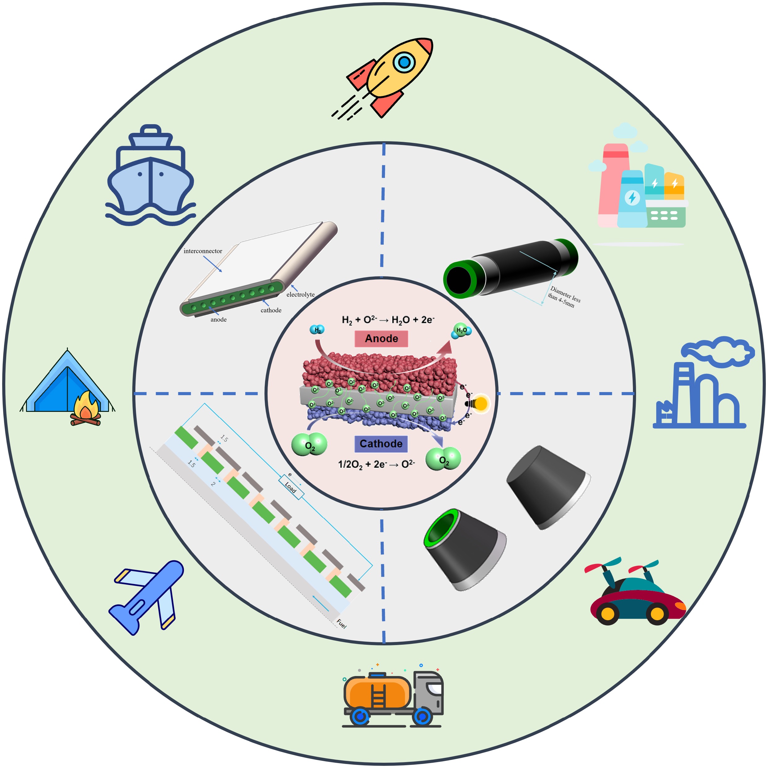
Due to the increasing global population and technological advances, the world’s energy demand is sharply increasing. Consequently, substantial amounts of pollutants, such as CO2, CO, and NOX are emitted into the atmosphere. In response to these environmental challenges, major economies have committed to ambitious climate targets, most notably the 'Carbon Neutrality 2050' initiative. Driven by these global policy frameworks, building highly efficient energy systems and exploring green energy sources are receiving a great deal of attention[1]. Hydrogen is widely accepted as a promising clean energy carrier to achieve carbon neutrality. Fuel cell technology is one of the major routes to convert hydrogen into electricity, with efficiencies unrestricted by the Carnot cycle[2]. Fuel cells can be categorized according to their operating temperatures, with low-temperature fuel cells including proton exchange membrane fuel cells (PEMFCs), alkaline fuel cells (AFCs), and phosphoric acid fuel cells (PAFCs), and high-temperature fuel cells including molten carbonate fuel cells (MCFCs) and solid oxide fuel cells (SOFCs)[3]. Compared with other types, SOFCs display some unique features, such as the generation of high-quality waste heat, improved efficiency, etc.[4,5]. In addition, the high working temperatures (around 700 °C) enable the utilization of numerous fuels, including hydrocarbons, biogas, and ethanol/methanol, thus significantly extending their potential applications[6].
Among various geometries of SOFCs, tubular and planar SOFCs have been most extensively investigated[7], as shown in Fig. 1. At present, commercial SOFCs predominantly adopt planar design[8]. The power level of the planar SOFC stack/system developed by Ceres Power and Hexis reached the kW level and has operated stably for over 10,000 h[9−12]. NASA successfully demonstrated a planar SOFC stack with a power density of 1.37 kW kg−1[13]. However, weak thermal cycling stability and intricate sealing requirements are two major issues that limit the widespread use of planar SOFCs[14]. In contrast, tubular SOFCs are easy to seal and demonstrate robust thermal cycling stability[15]. Additionally, tubular structures feature faster start-up and shut-down, higher mechanical strength, and superior thermal cycling stability[16,17].
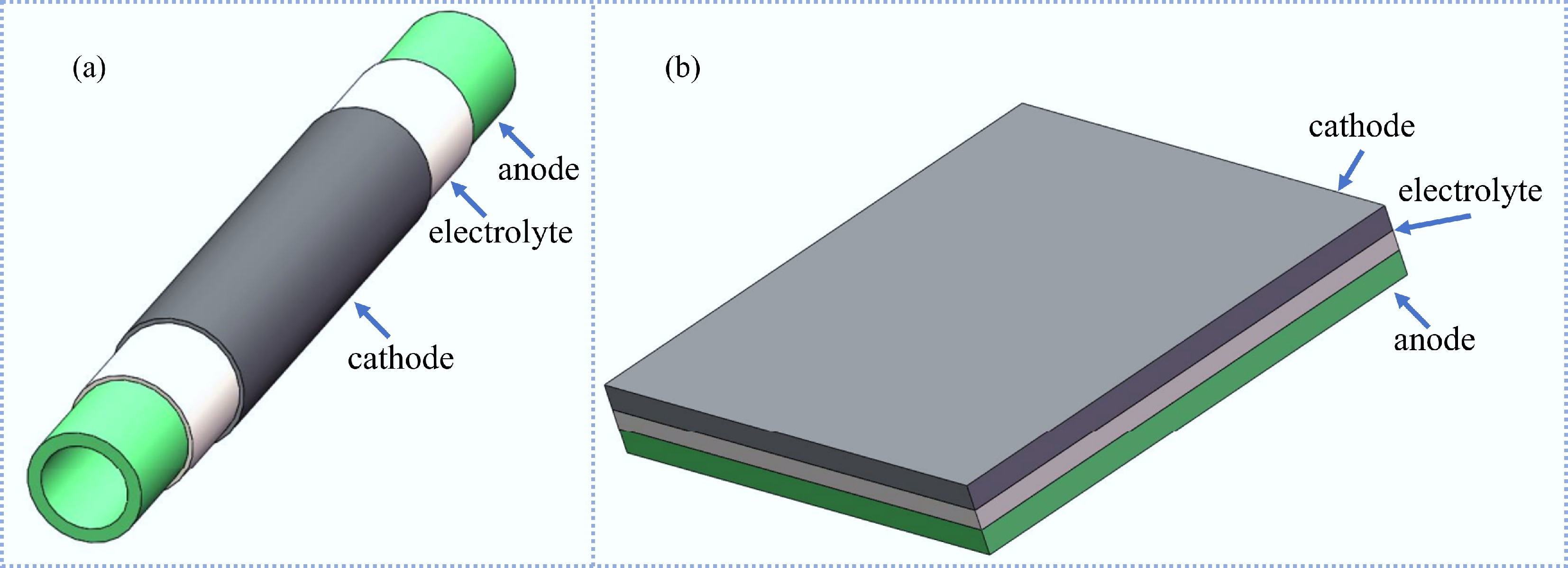
Figure 1.
Schematic of SOFC: (a) tubular structure, (b) planar structure.
Tubular SOFCs emerged in the 1960s[18], and the cathode-supported tubular SOFCs manufactured by Westinghouse were a typical representative of the early examples of tubular SOFCs[19]. Although Westinghouse has stopped research on tubular SOFCs, the feasibility and potential of this technology have been well demonstrated through the fabrication of the single cell and systematic testing on both single cells and stacks. Despite a reported operational lifespan beyond 20,000 h[20], the power density of tubular SOFCs remained relatively low owing to inefficiencies in cell stacking and elongated electrical pathways resulting in high cell losses[21]. To improve performance, intense research efforts have focused on exploring novel materials and geometrical designs. State-of-the-art tubular SOFCs have achieved a peak power density of 2 W cm−2 (at 700 °C with low calorific value gases)[22], facilitating their adoption in multiple practical fields.
Yet, a systematic overview covering the fabrication, stacking, and application distinctions among different tubular geometries is still limited in the literature. In this review, fabrication methods for single-cell and stack assembly designs are comprehensively described. In addition, practical applications of tubular SOFCs are outlined, such as in transport applications, cogeneration based on tubular SOFCs, integration with gas turbines, and emerging energy technologies. Finally, current challenges to be addressed and future directions are presented.
-
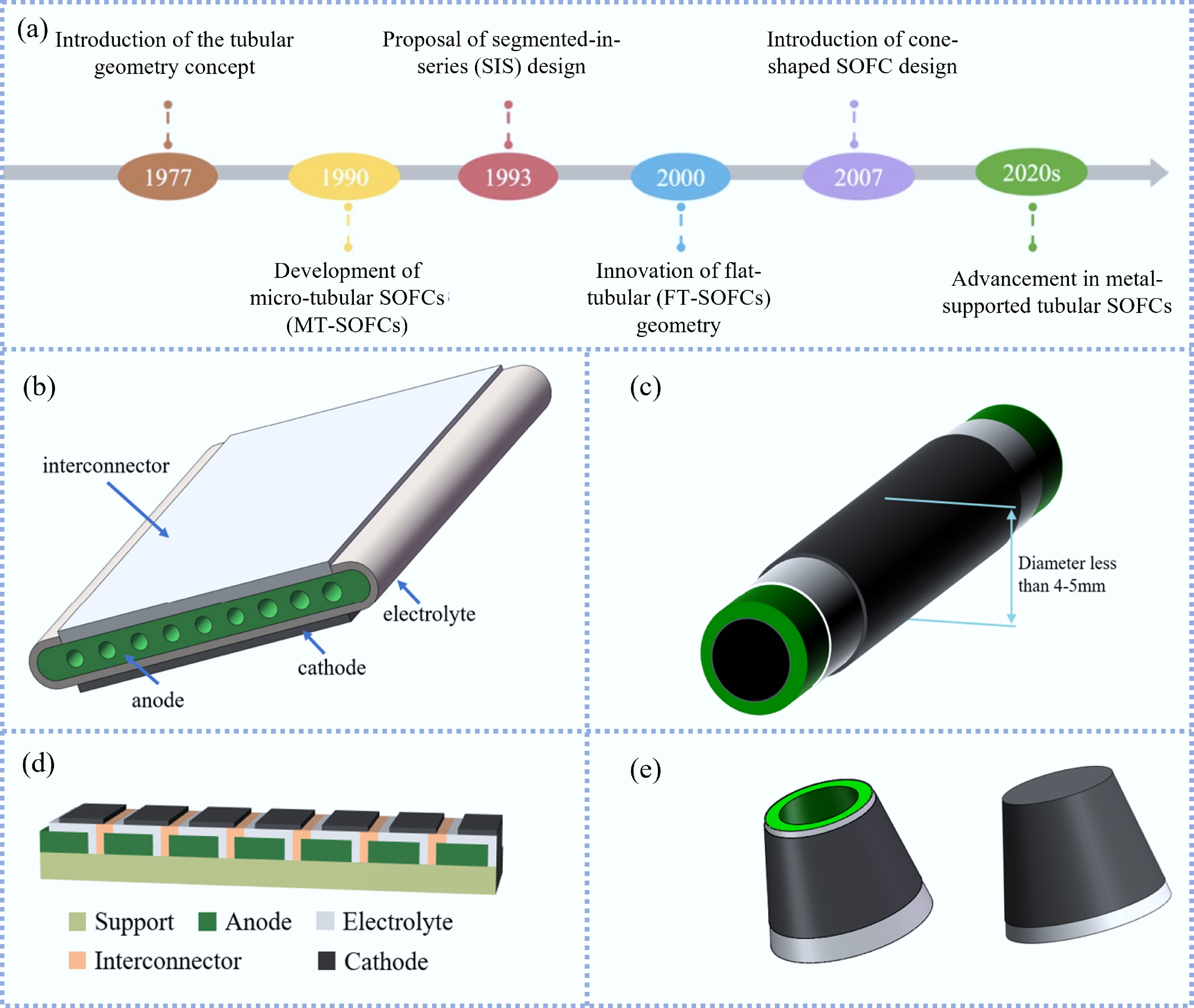
The structural design of tubular SOFCs has undergone significant evolution to enhance mass transport and electrochemical performance. Initially, Westinghouse Electric Corporation fabricated tubular SOFCs by depositing thin layers of cell components on a porous calcia-stabilized zirconia support[23]. Although the porous support tube (PST) allowed air to pass through to the cathode, it still created resistance to the passage of gas. To facilitate the diffusion of air, the thickness of the PST was reduced, and then the PST was replaced with a cathode support tube. The performance of the tubular SOFCs with cathode support was significantly improved. Westinghouse conducted numerous long-term tests of the tubular SOFCs. After 25,000 h of testing, the tubular SOFCs exhibited a performance degradation of approximately 0.1% per 1,000 h. The cell exhibited no mechanical damage or performance loss after conducting over 100 thermal cycles, ranging from 1,000 °C to room temperature[24]. These results were crucial for the commercialization of tubular SOFCs. Meanwhile, a pressure test was carried out on the tubular SOFCs, and the performance was obviously improved under a working pressure of 15 atm. Since Westinghouse proposed the initial generation of tubular SOFCs, researchers have developed various innovative types of tubular SOFCs over the past decades, including flat-tubular SOFC (FT-SOFC), cone-shaped SOFC, segmented-in-series SOFC (SIS-SOFC), and micro-tubular SOFC (MT-SOFC). Each geometry exhibits unique advantages and characteristics. The diversified geometries of tubular SOFCs demonstrate applicability in various scenarios. The timeline for the development of various tubular SOFCs and the schematic diagram of SOFC with various geometries are shown in Fig. 2.
Flat-tubular SOFC
-
The FT-SOFC represents a strategic structural evolution designed to enhance electrochemical performance by optimizing the current collection path. For instance, building upon the conventional tubular architecture[19], this configuration was developed to maximize volumetric power density while retaining mechanical robustness[4]. The FT-SOFC functions as a hybrid design, combining the sealing advantages of tubular cells with the high active area of planar geometries[28]. The anode generally serves as the support of the FT-SOFC, including multiple fuel flow channels[29], as shown in Fig. 2b. In addition to the circular current on both sides, the ribs between the anode channels exhibit electronic conductivity and provide a short path for current collection. This characteristic of the FT-SOFC results in dramatically reduced ohmic resistance and significantly enhanced power density compared to its traditional tubular counterpart. Structurally, the fuel gas and air are segregated by a dense interconnector film on one side of the cell, which interfaces with the cathode of the adjacent cell to establish a series connection, thus enabling stack assembly.
The single-cell
-
Extensive research has focused on optimizing the geometric design and fabrication parameters of anode-supported FT-SOFCs to maximize their electrochemical output and structural advantages (Table 1). To effectively exhibit the advantages of the FT-SOFC, Lim et al.[30] conducted a performance comparison of a tubular SOFC and an FT-SOFC with the same NiO-YSZ/YSZ/LSM-YSZ/LSM/LSCF structure prepared by the extrusion method. When the voltage was 0.7 V, the corresponding power density of the tubular SOFC was around 0.21 W cm−2, whereas the FT-SOFC reached 0.39 W cm−2 at 750 °C with humidified H2 as fuel, representing an approximately 85.7% improvement in performance. This was due to the presence of ribs in the anode, shortening the path of current transfer. Suzuki et al.[6] fabricated a micro FT-SOFC with a NiO-YSZ anode as support, ScSZ electrolyte, GDC interlayer, and LSCF-GDC cathode. When 20% H2 in Ar was used as the fuel, the peak power density of the cell was 0.546 W cm−2 at 700 °C. Kim et al.[31] used the extrusion method to fabricate a NiO-YSZ anode support, and then the surface of the support was modified by dip-coating a fine powder-sized NiO-YSZ slurry to make the pores uniformly distributed. The remaining cell components were prepared by dip-coating. The final cell produced a maximum power density of 0.56 W cm−2 at 850 °C. Park et al.[32] utilized the extrusion technique to manufacture the anode support. Following pre-sintering, a grinding wheel was used to carve one side of the support to form airflow channels to make assembly simpler. The final cell is shown in Fig. 3a and provided a peak power density of 0.498 W cm−2 at 700 °C. Wang et al.[33] utilized the extrusion method to manufacture the anode support, and the cell components were prepared by screen printing. With the structure of Ni-YSZ/YSZ/GDC/LSCF-GDC, the final cell produced a peak power density of 0.539 W cm−2 at 750 °C. Yoon et al.[34] compared the performance of an FT-SOFC without and with an interconnector. The schematic diagram of the cell is shown in Fig. 3b. The maximum power density of the FT-SOFC without an interconnector was 0.798 W cm−2. When the cell contains the interconnector, the ohmic impedance increases, resulting in a decrease in performance to 0.566 W cm−2.
Table 1. Comparison of peak power densities and geometric parameters of anode-supported FT-SOFCs reported in recent literature
Type Cell composition Maximum power density (W cm−2) Test temperature (°C) Ref. FT-SOFC NiO-YSZ/YSZ/LSM-YSZ/LSM/LSCF 0.39 750 [30] FT-SOFC NiO-YSZ/ScSZ/GDC/ LSCF-GDC 0.546 700 [6] FT-SOFC NiO-YSZ/YSZ/LSCF-GDC 0.498 700 [32] FT-SOFC Ni-YSZ/YSZ/GDC/LSCF-GDC 0.539 750 [33] FT-SOFC NiO-YSZ/YSZ/LSM-YSZ 0.798 750 [34] 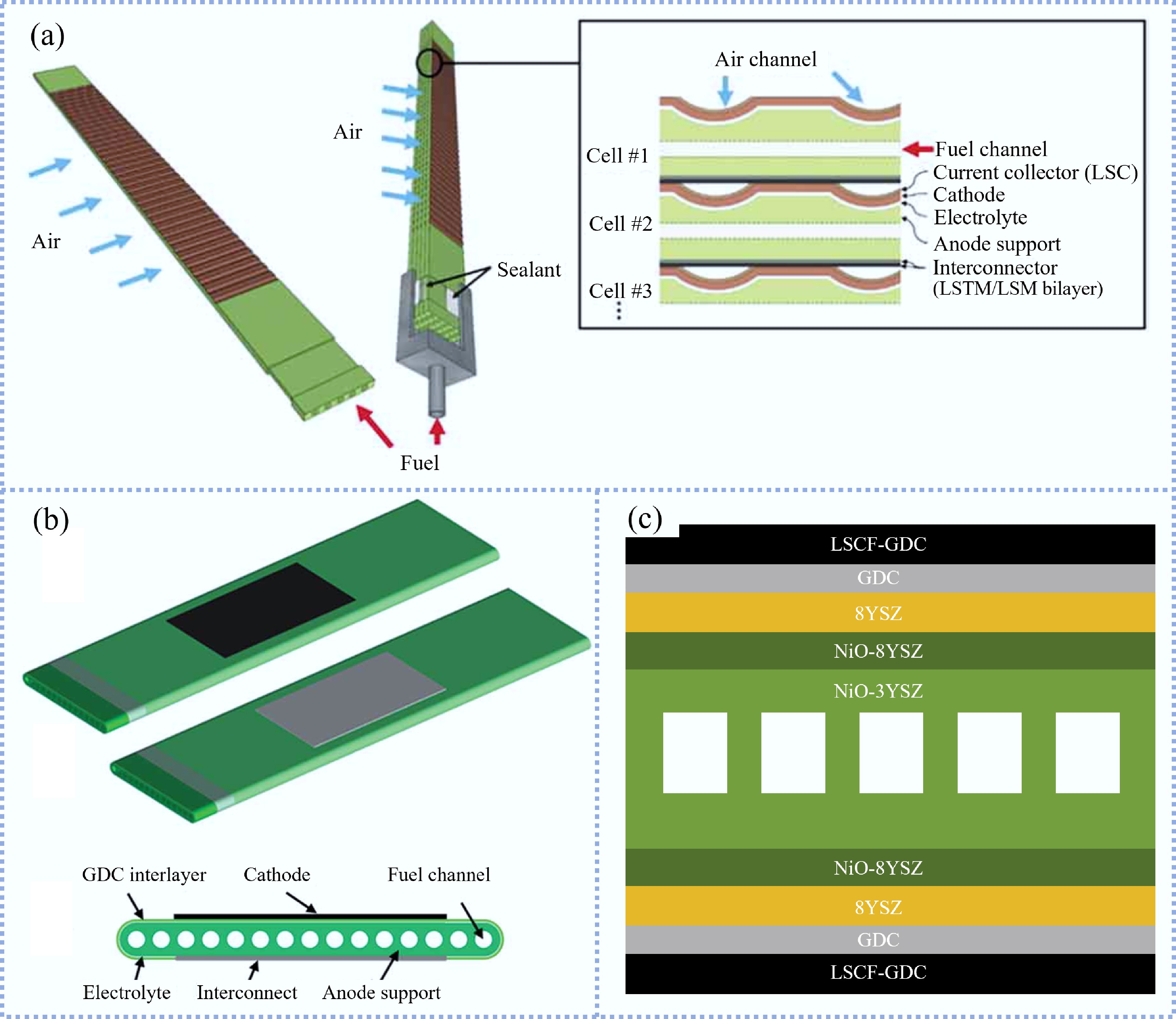
In practice, SOFCs face problems such as start-stop cycles, maintenance, and operating temperature changes. Therefore, the redox stability and thermal cycle stability of SOFCs are very important. Guan et al.[35,36] proposed the symmetrical FT-SOFC, as shown in Fig. 3c, which can maintain uniform thermal stress on both sides of the flat tube support to ensure the integrity of the cell. Subsequently, the influence of thermal cycling on cell performance was investigated, and the results indicated that the weak contact between cathode and interconnect was the primary cause of performance degradation[37]. This issue can be mitigated by applying a load on the cathode side, and it was found that the performance of the cell was superior to the initial value. During the durability test of the symmetrical FT-SOFC, a total of 2,030 h of operation was conducted under the conditions of discharging at 28 and 21 A, and the performance dropped by about 20%[38]. Khan et al.[39] studied the degradation behavior of an FT-SOFC during long-term operation at constant current densities, which was evaluated through voltage loss. The results showed that operating at high current densities can result in accelerated degradation due to enhanced Ni particles coarsening in the anode, the formation of an insulating phase between cathode and electrolyte, and the evolution of fine particles in the cathode. Therefore, discharging at low current density was a better choice to ensure the stable operation of the cell.
FT-SOFC stacks
-
Overall, recent progress in FT-SOFC stack development has focused on scaling up cell number and active area while innovating interconnection and sealing architectures, enabling peak stack power to increase from the sub-kW level to ~1 kW at 700–750 °C, albeit sometimes at the expense of volumetric power density. Lim et al.[40] fabricated an FT-SOFC stack consisting of 24 cells, producing a peak power output of 507 W. On this basis, a stack design in which two single cells were connected in parallel into a unit bundle was proposed and verified for further scale-up, as shown in Fig. 4a[30]. Subsequently, a stack with an active area of 5,400 cm2 was assembled, as shown in Fig. 4b, producing 921 W peak power output at 750 °C using humidified H2 as fuel[30]. The stack manufactured by Ji et al.[41] was composed of FeCrAl metal flat boxes and five cells were located on the surface of a metal box, which was sealed to the metal box through Ag-Cu air brazing, as shown in Fig. 4c. The final stack produced a peak output power of 614 W. This method provided a new idea for fabricating an FT-SOFC stack, but it leads to a degradation in the volumetric power density of the stack. Park et al.[32] prepared an FT-SOFC stack consisting of five of the monolithic electrodes and gas channels assembly cells. The innovative design enabled single cells to be assembled into stacks like planar SOFCs, which can shorten the current path. The stack achieved a peak output power of 46.2 W. Choi et al.[42] utilized metallic components to assemble a 30-cell stack with a 3,000 cm2 active area, as shown in Fig. 4d. The metallic components not only functioned to maintain mechanical integrity but also helped with stack sealing. The power output of the stack reached 1 kW at 700 °C. Han et al.[43] investigated the effects of constant-current/constant-voltage discharge on stack performance using a three-cell stack with an active area of 180 cm2, and a peak power of 103.5 W was obtained at 750 °C. The results indicated that the degradation rate of the stack performance was lower when the stack was operated in constant-current operation mode.
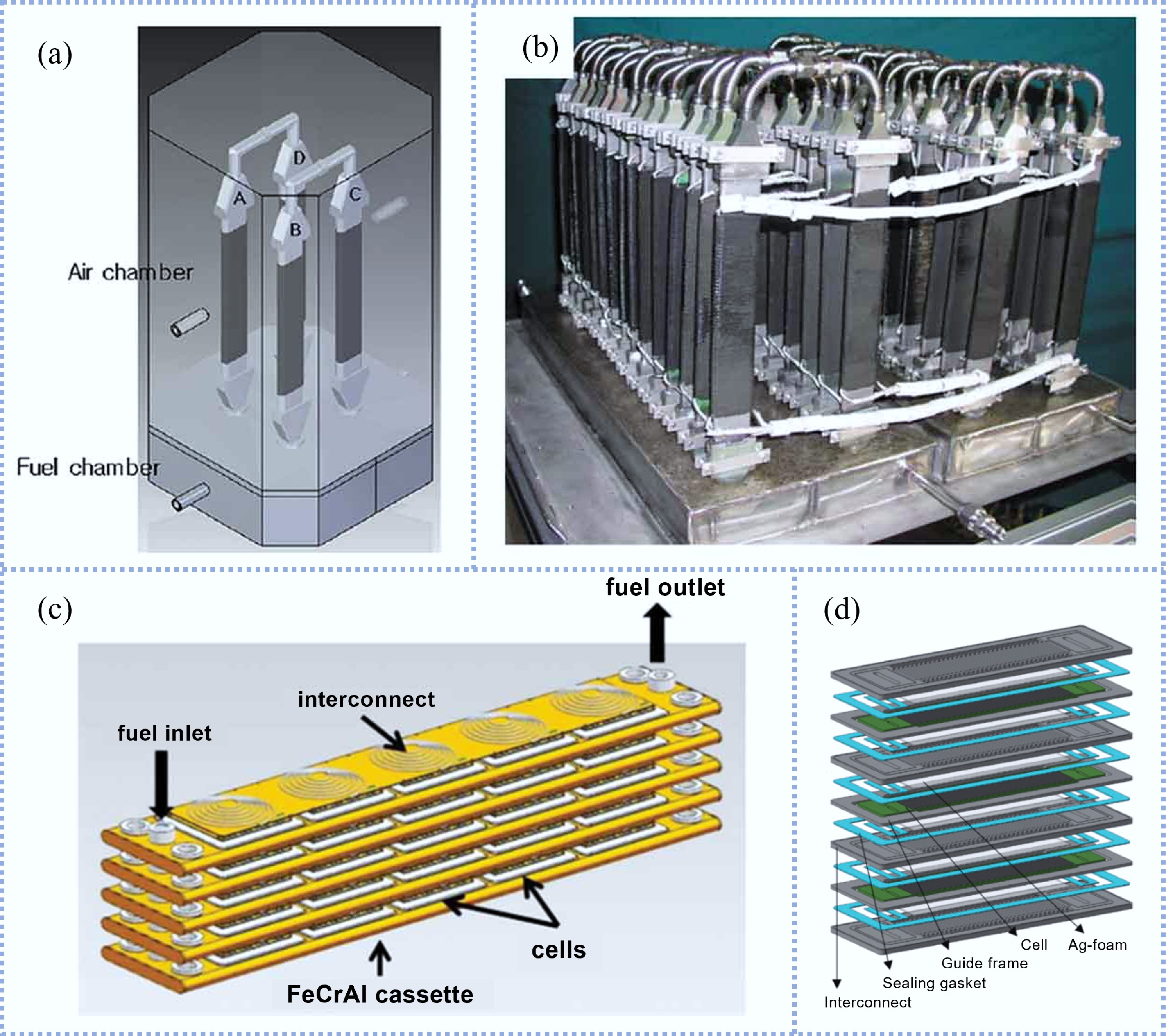
Figure 4.
(a) Schematic diagram of a two-unit bundle containing four cells, and (b) actual image of the 1 kW class FT-SOFC stack[29]. (c) Schematic diagram of stack structure[29]. (d) Schematic diagram of the stack components[42]. (Reprinted with permission from Han et al.[43]. Copyright [2022] Elsevier B.V.)
Cone-shaped SOFC
-
In pursuit of attaining a higher voltage within a limited space, Sui & Liu first proposed the concept of the cone-shaped SOFC, as shown in Fig. 2e[27]. In this innovative design, one cell is fitted into the following cell to form a tubular self-supporting structure[27]. Therefore, the cone-shaped SOFC can be considered as an improved tubular SOFC, retaining the structural characteristics of the tubular design while providing elevated thermal stability[28]. In this design, the interconnect is positioned between the anode of one cell and the cathode of the subsequent one, functioning as both a sealing and an electrical connection. During stack assembly, the substantial quantity of cone-shaped SOFCs makes connection sealing a notable challenge in this design. During stack operation, the fuel flows from the interior of one cell to the interior of the subsequent one, while the air flows on the exterior.
Sui et al.[27] utilized the slip casting technique to prepare a YSZ electrolyte support. The NiO-GDC anode and LSCF-GDC cathode were deposited on the inner and outer sides of the electrolyte support, respectively. The three-cell stack with an active area of 15.9 cm2 produced a peak power of 0.9 W at 800 °C. Subsequently, Sui et al.[44,45] prepared a 0.196 mm-thick SDC electrolyte support and a 0.26 mm-thick GDC electrolyte support by slip casting, and the final cells produced a peak power density of 0.297 and 0.3 W cm−2 at 700 °C, respectively. In general, the performance was not as good as the tubular counterpart due to a thicker electrolyte, resulting in larger ohmic losses. In order to overcome this problem, Zhang et al.[46] utilized slip casting technology to prepare a cone-shaped anode tube, and then a 20 μm-thick YSZ electrolyte was fabricated by dip-coating technology. The ohmic losses from the thin electrolyte membrane were negligible, and the final cell reached a peak power density of 1.15 W cm−2 (at 850 °C with moist hydrogen). Bai et al.[47] used dip-coating technology to fabricate a cone-shaped SOFC anode support and a 35.9 μm-thick YSZ electrolyte. The cell achieved a peak power density of 1.35 W cm-2 at 850 °C with moist hydrogen. The fabricated stack consisting of two cells with an active area of 11.6 cm2 produced a peak power of 3.7 W at 800 °C. Ding et al.[48] utilized the slip casting technique to prepare a NiO-YSZ anode substrate; the NiO-YSZ functional layer and a 6.67 μm-thick YSZ electrolyte film were fabricated by the dip-coating method. The final cell exhibited a peak power density of 1.78 W cm−2 at 800 °C. On this basis, the maximum power of the two-cell stack with an active area of 10.65 cm2 exceeded 2.75 W at 800 °C and showed superior thermal cycling stability. It can be concluded that the utilization of an anode support enables a reduction in electrolyte thickness, consequently enhancing the cell performance. Ding & Liu[49] also used a one-step co-sintering process to manufacture a cone-shaped SOFC, reaching a peak power density of 0.797 W cm−2 at 850 °C. The co-sintering method greatly reduces the preparation process and fabrication costs.
The process of fabricating anode support by the slip casting method is complex, while the dip-coating method is time-consuming. In comparison, the gel injection molding technique is a superior alternative. Liu et al.[50] used the gel-casting technique to prepare the cone-shaped anode support, which can obviously reduce cell production time. The final cell produced a peak power density of 0.9 W cm−2 at 800 °C. On this basis, the four-cell stack with an active area of 16.2 cm2 produced a peak output power of 3.4 W at 800 °C. In addition to the above-mentioned technologies, low-pressure injection molding technology[51] and the phase inversion method[52] can also be used to manufacture the cone-shaped SOFCs.
Segmented-in-series SOFC
-
In recent years, large-scale hybrid power systems based on SOFC technology have been developed. The hybrid system requires a high voltage during operation, but the output voltage that a cell can provide during regular operation is around 0.7–0.8 V, which is far less than the voltage required by the system. To meet the voltage required by the system, multiple cells need to be connected in series, which is a complicated process. SIS-SOFC integrates multiple cells onto a support, which can obtain high output voltage at low current, further reducing ohmic loss[53]. Rolls-Royce initially proposed the concept of segmented-in-series SOFC (SIS-SOFC)[54], The schematic diagram of SIS-SOFC is shown in Fig. 2d. SIS-SOFC includes tubular and flat tubular designs. This geometry structure can provide many advantages, such as: (1) high resistance to redox cycles from ceramic supports; (2) simple sealing; (3) no additional components required with integrated interconnect[55,56].
The extrusion method is a widely used method for fabricating flat tube supports, Mushtaq et al.[57] used the extrusion method to fabricate a 3YSZ flat tube as support, and the cell components were prepared by screen printing and dip-coating. The detailed preparation process is shown in Fig. 5a. The cell with varying cathode thicknesses exhibited different electrochemical properties, and the optimal performance of the SIS-SOFCs composed of five cells was 0.498 W cm−2 obtained at a cathode thickness of 57 µm. Kim et al.[58] used the same method to fabricate the SIS-SOFC. The peak power density and peak output power of the five-cell unit bundle were 0.618 W cm−2 and 2.47 W, respectively. Fujita et al.[59] fabricated an SIS-SOFC with a flat tube support. The cell comprised Ni-doped MgO-based support, NiO-YSZ anode, YSZ electrolyte, and LSCF cathode. With reformed methane used as fuel, the average power density of the SIS-SOFC was 0.195 W cm−2 at 0.24 A cm−2. A total of 20 redox cycles were conducted, with only 0.15% performance loss per cycle despite supplying air directly as the oxidant to the anode side. The excellent redox tolerance was due to the fact that the substrate can prevent the diffusion of oxygen, and the presence of Ni in the substrate prevents the anode from being oxidized. Later, Fujita et al.[60] reported that the Ni-doped MgO-based support of SIS-SOFC can prevent the deformation of the cell and thus exhibit high redox tolerance.
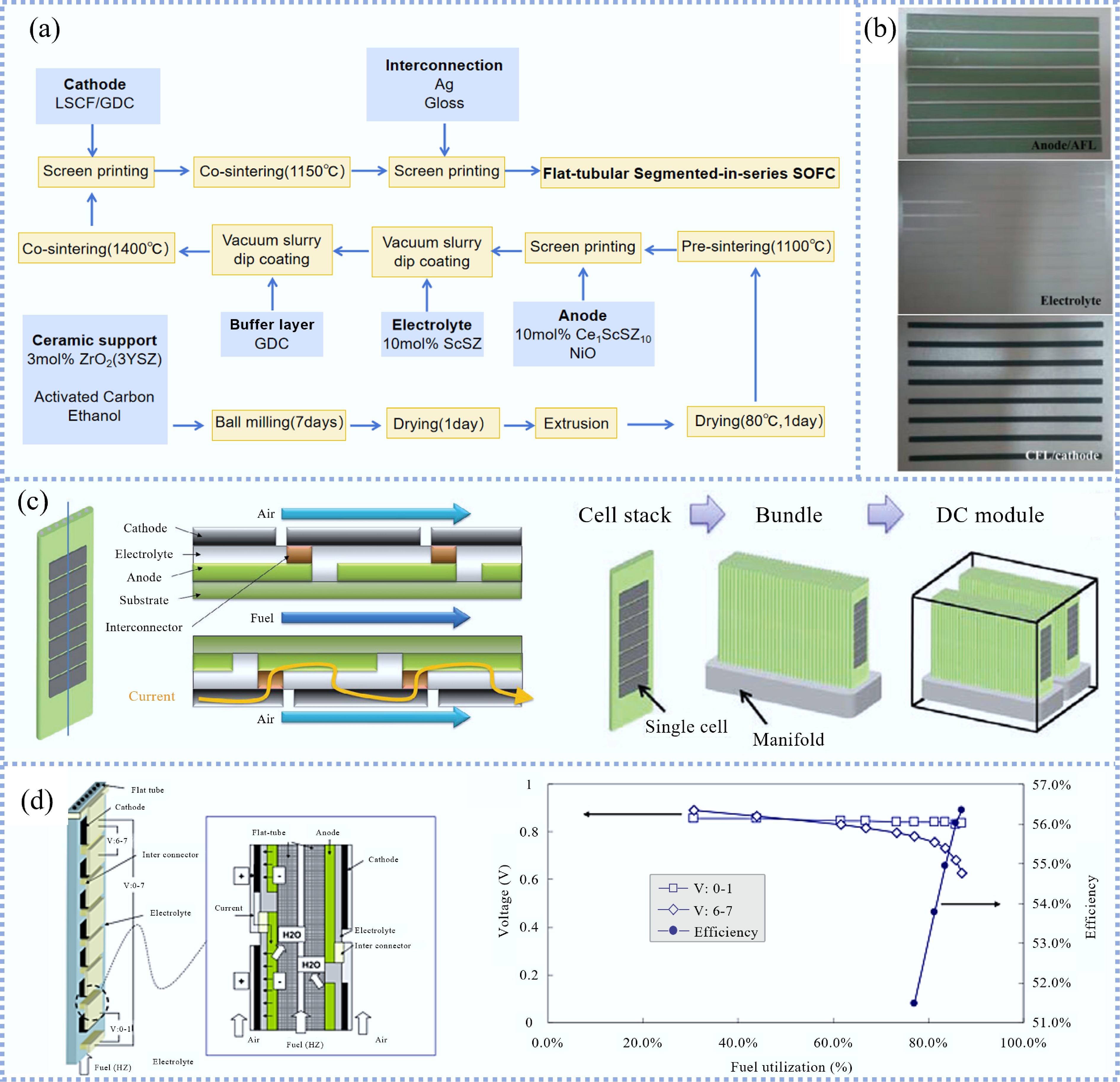
Figure 5.
(a) Process of preparing SIS-SOFC. (b) Cell components fabricated by decalcomania papers method[61]. (c) Schematic of the tubular SIS-SOFC and the stack with 56 tubular SIS-SOFCs[29]. (d) Schematic diagram of the SIS-SOFCs stacks consist of 14 cells, and the influence of fuel utilization on voltage. V: 0–1 and V: 6, 7 represent the voltage of the cell at the most upstream and most downstream cell, respectively[68].
In addition to the above mainstream methods, An et al.[61] used the extrusion method to prepare a YSZ support, and the cell components were fabricated by the decalcomania paper methodology, as shown in Fig. 5b. This method allowed the preparation of SIS-SOFCs on all sides of the support, and the thickness and shape of the components can be controlled. The peak power density of the two-cell stack was 0.437 W cm−2 at 800 °C. Pillai et al.[62] fabricated a PSZ flat tube support by the gel-casting method, and cell components were prepared by screen printing. The final cell produced a peak power density of 0.7 W cm−2 at 800 °C. Kim et al.[63] utilized a direct-writing technique based on selective paste dispensing to prepare cell components on a PSZ support. Compared with traditional methods, this method can improve control over the microstructure. The two-cell SIS-SOFCs produced a peak power of 35 mW at 800 °C at an anode-cathode overlap area of 0.5 cm × 0.1 cm. The open circuit voltage was lower than the theoretical value due to the presence of pores in the interconnects. To address this issue, double-layer interconnects and Ag-glass interconnects have been studied and demonstrated reliable sealing performance[56,64,65]. Zhang et al.[53] used thermal spraying to fabricate SIS-SOFC on an end-close tubular support as shown in Fig. 5c. The dense interconnectors in the closed section of the support can act as a seal, and the open end was in a relatively low-temperature region during operation, making sealing easier. The optimal value of the quantity of cells in series was determined through theoretical analysis. On this basis, a tubular support with an inner diameter of 21 mm was manufactured with 20 cells connected in series. Subsequently, as shown in Fig. 5c, a stack composed of 56 SIS-SOFCs was fabricated and the output power of the stack exceeded 800 W at 830 °C.
Additionally, several companies have conducted research and experimental tests on SIS-SOFC. Mitsubishi Hitachi Power Systems (MHPS)[66] fabricated an SIS-SOFC stack that exhibited excellent stability performance. Operating under normal pressure for more than 7,000 h, the degradation rate per 1,000 h was less than 0.25%. Based on this work, an integrated system with a micro-turbine was developed. Tokyo Gas and its partner company[55] developed a SIS-SOFC stack with an output power of more than 400 W, with a cell degradation rate of approximately 0.31% per 1,000 h. Kyocera Corporation (Japan) conducted a 100,000-h durability test on an FT-SOFC, which was the longest test to date[67]. The performance gradually degraded without sudden changes.
For SIS-SOFCs, multiple cells are arranged on a substrate and the cells located at the upstream consume fuel, resulting in low fuel density for downstream cells, which negatively affects the downstream cells. Koi et al.[68] manufactured SIS-SOFCs consisting of 14 single cells. The cells were divided into two groups on both sides of the insulating substrate with the structure of NiO-YSZ/YSZ/LSCF, as shown in Fig. 5d. With high fuel utilization, the voltage of downstream cells was significantly lower than that of upstream cells. To solve this problem, Cui et al.[69] established a model of SIS-SOFC to optimize the voltage distribution. The simulation results demonstrated that with the active area of the cell gradually increasing along the flow direction of fuel, the downstream cells can maintain a higher voltage under the same current operation. Therefore, this method can alleviate the problem of voltage non-uniformity. Fan et al.[70] set up heat pipes to transfer heat from high-temperature regions to low-temperature regions to diminish the temperature gradient of the cell. Based on the calculation formula of open circuit voltage, it can be concluded that reducing the temperature gradient can alleviate the problem of voltage nonuniformity.
Micro-tubular SOFC
-
Compared with the traditional tubular SOFC, the micro-tubular design exhibits a higher power density per unit volume, rapid start-up and shut-down and high thermal shock resistance[23,71]. Therefore, MT-SOFC has received widespread attention during the past decades. MT-SOFC was initially reported by Kevin Kendall at the beginning of the 1990s[26]. Essentially, as shown in Fig. 2c, MT-SOFCs can be considered as the miniaturization of traditional tubular SOFCs to the millimeter scale, typically around 5 mm. Hence, MT-SOFC is a preferred choice for portable devices. The design of the microtubular structure proves effective in significantly increasing the specific surface area. Nevertheless, the small diameter of the micro-tube poses challenges for current collection and stack assembly. Despite this challenge, researchers have successfully demonstrated the feasibility and great potential of this state-of-the-art design.
The single-cell
-
The first generation MT-SOFC mainly used the electrolyte layer as support[26]. However, the thick electrolyte layer led to significant ohmic resistance that limited performance. Subsequently, the anode-supported design had become widely adopted since the thickness of the electrolyte layer could be dramatically decreased down to < 10 μm to achieve high-performance.
The classic process for fabricating anode support by the extrusion method is to mix ceramic powder, polymer and a pore-forming agent into a slurry, and then the slurry is extruded from the mold using an extruder to prepare the anode support. Suzuki et al.[72] fabricated an MT-SOFC by the extrusion method; the porosity of the anode before reduction was approximately 30%. With a structure of NiO-GDC/GDC/LSCF-GDC, the cell produced a peak power density of 0.857 W cm−2 at 550 °C. The porosity of the anode can affect the mass transfer capacity of fuel gas. Especially at high gas flow rates, the porosity has a significant effect on cell performance[73]. To increase the porosity of the anode, polymethyl methacrylate beads were incorporated into the anode slurry, which increased the porosity to 46% before reduction, and the pores diameters were evenly distributed[74]. An Ag wire was used to collect current from the electrodes, where the current collection from the anode was only from the edge of the anode tube. The cell produced a peak power density of 1.017 W cm−2 at 550 °C. Collecting current from the edges of the tube led to a loss of current collection, Sin et al.[75] positioned the current collecting wires throughout the anode tube. The final cell produced a peak power density of 1.31 W cm−2 at 550 °C. Calise et al.[76] used a similar process to fabricate an MT-SOFC, which was tested vertically to overcome non-uniform distribution of fuel gas due to gravity. The cell produced a peak power density of 1.31 W cm−2. With the improvement of the fabrication process, the performance of MT-SOFC manufactured by the extrusion method has gradually improved, which illustrated the applicability of the extrusion method in the MT-SOFC manufacturing process.
The extrusion method allows the fabrication of multilayer structures of MT-SOFC in a one-step process. Kendall[71] reported the fabrication of electrolyte-supported MT-SOFC through the co-extrusion technique. Sun et al.[77] successfully fabricated a NiO-YSZ/YSZ dual-layer micro-tube through thermoplastic co-extrusion. The outer diameter of the tube can be adjusted in the range of 0.4–1.8 mm. Simultaneously, as the diameter of the tube decreased, the thickness of the electrolyte became thinner while maintaining density. Rahman et al.[78] fabricated an MT-SOFC with a diameter of 4.2 mm using the co-extrusion method. The manufacturing process and the actual images of MT-SOFC with seven cells are shown in Fig. 6a. The tube can be viewed as an assembly of seven cells, with the outer layer as anode, the YSZ electrolyte and LSM cathodes were deposited on the interior surface of the seven channels. Mani et al.[79] designed a co-extruder capable of simultaneously fabricating a five-layer structure. The multi-layer anode was segmented into four layers with different nickel content. Unfortunately, the performances of the above-mentioned MT-SOFCs manufactured through the co-extrusion method are not reported, making it uncertain to assess the applicability of the co-extrusion method in MT-SOFC manufacturing.
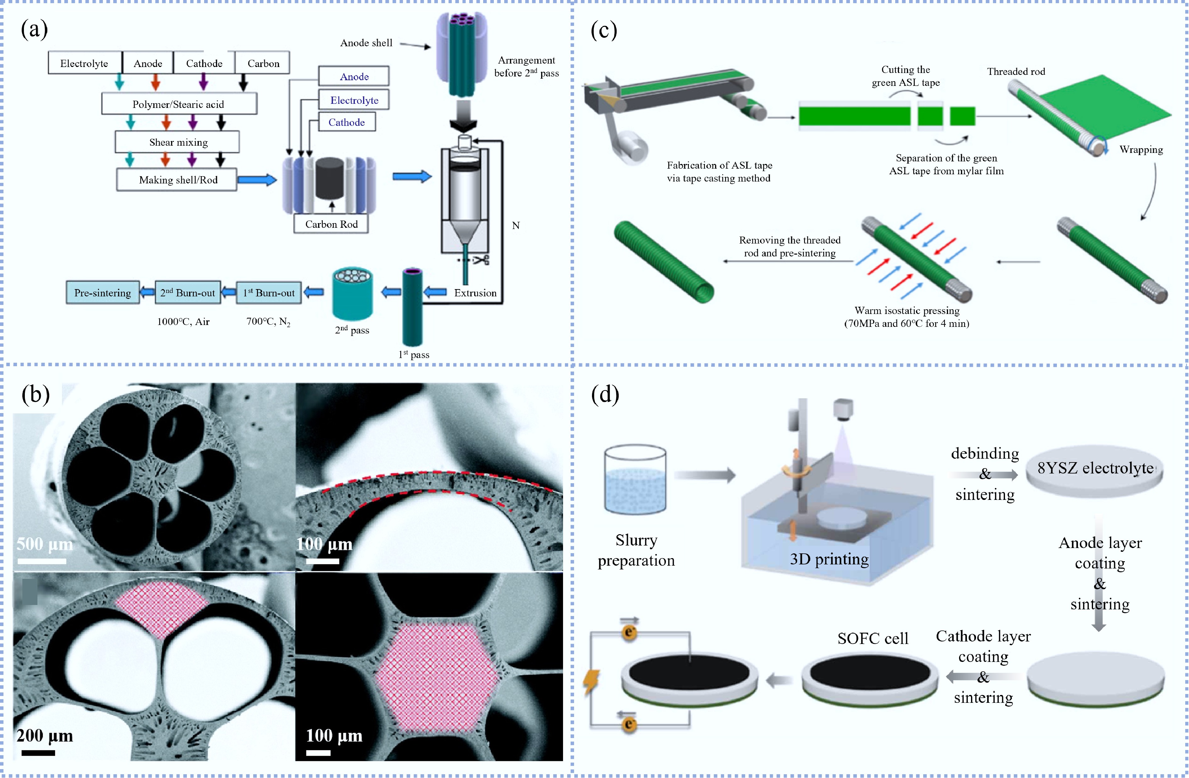
Figure 6.
(a) Fabricating process of multi-tubular SOFC with seven cells[78] (Reprinted with permission from Mani et al.[79]. Copyright [2010] Elsevier B.V.). (b) SEM photomicrographs of 6-channel anode supports[22]. (c) Fabrication steps of anode support bolt-microtube[83] (Reprinted with permission from Kim & Jang[84]. Copyright [2023] Elsevier B.V.). (d) Schematic of 3D printed MT-SOFC fabrication process[84].
Aside from ram extrusion, the phase inversion-assisted extrusion method has proven to be a promising alternative for MT-SOFCs manufacturing. Compared to the conventional ram extrusion, the phase inversion method allows for flexible control and tailoring of the micro-structure of ceramic tubes. The phase inversion method was initially utilized to manufacture polymer membranes[80]. Tan et al.[81] first reported the application of the phase inversion method to manufacture ceramic membranes in 2001. Wei & Li[82] utilized the phase inversion method to prepare YSZ hollow fiber membranes as support for MT-SOFC, which featured a typical asymmetric structure. The finger-like structure near the inner surface increased the area loaded with Ni, while the sponge-like structure near the outer surface becomes completely dense after sintering, ensuring excellent gas tightness. However, due to the YSZ dense layer thickness reaching 120 μm, resulting in high ohmic loss and only a maximum power density of 0.018 W cm−2 was obtained at 800 °C. Therefore, most researchers turned attention to anode-supported hollow fiber MT-SOFC.
Droushiotis et al.[85] used the phase inversion method to prepare a NiO-YSZ anode and found that the mechanical property of the hollow fiber membranes dropped with rising Ni content. Othman et al.[86] investigated eight types of the anode with different lengths of finger-like layers. The result showed that a long finger-like layer enhanced gas diffusion but reduced the electrical conductivity and bending strength of the membrane. Thus, it was evident that the configuration of finger-like layers in the anode had an obvious impact on the overall anode performance. Chen et al.[87] utilized a graphite-assisted phase inversion method to prepare a NiO-YSZ anode with a porosity gradient to alleviate the concentration polarization at high current density. Compared with the original cell, the optimized cell exhibited enhanced electrochemical performance, with the peak power density increasing from 0.51 to 0.66 W cm−2 at 850 °C. Notably, concentration polarization had been significantly mitigated at high current density. Yang et al.[88] utilized the phase inversion method to fabricate a Ni-YSZ anode with dual pore structures. The exterior region of the anode, adjacent to the YSZ electrolyte layer, had small finger-like pores, which were regarded as the site of electrochemical reactions. Meanwhile, large finger-like pores on the interior contribute to enhancing fuel gas transfer. The final cell produced a maximum power density of 0.78 W cm−2 at 800 °C. Li et al.[22] fabricated the multi-channel MT-SOFC using the phase inversion method, as shown in Fig. 6b. This innovative structure enabled MT-SOFC to exhibit outstanding mechanical robustness compared to single-channel MT-SOFC. Unlike the traditional structure, this structure distributed the support between electrochemically active regions and the central area, reducing the mass transfer resistance. According to the nitrogen permeation results, the multi-channel anode demonstrated superior gas transport capabilities compared to the single-channel structure[8]. The fabricated six-channel MT-SOFC with the structure of NiO-YSZ/YSZ/GDC/LSCF-GDC, reached a peak power density of 2.27 W cm−2 at 700 °C. Through optimizing the manufacturing process, Wang et al.[89] optimized the shape of the multi-channel to the tear-drop design. The novel structure further enhanced the mass transfer capability. However, this structure may reduce electrochemical reaction sites, hence the presence of an anode functional layer may be necessary.
Similarly, the phase inversion method allows the simultaneous preparation of multi-layer structures. Li et al.[90] fabricated a NiO-CGO (weight ratio 3:2) anode, a NiO-CGO (weight ratio 2:3) anode functional layer, and a CGO electrolyte using a triple-layer co-extrusion method. The influence of the thickness of the anode functional layer on cell performance was investigated, and the results indicated that a thicker anode functional layer can increase the mechanical robustness of the cell but affects the diffusion of fuel gases, resulting in a degradation of electrochemical performance. Rahman et al.[17] utilized a phase inversion-assisted co-extrusion method to manufacture MT-SOFC with NiO-YSZ/YSZ/LSM-YSZ in one step. Due to the different sintering characteristics of cell components, sintering at high temperatures will lead to a decline in cathode porosity. To solve this problem, YSZ powders with different particle sizes were used to manufacture different structures, and the ideal microstructure was obtained by adjusting the sintering temperature and heating rate. The maximum power density of the final cell was 0.75 W cm−2 at 700 °C.
Apart from the above-mentioned mainstream MT-SOFC manufacturing methods, there are also some other methods. Altan et al.[83] proposed the concept of bolt-microtubular SOFC and the fabrication process is shown in Fig. 6c. An anode support with unique patterns was fabricated on the threaded rod by tape casting combined with isostatic pressing, which increased the interface area between the electrode and electrolyte and provided more reaction sites. Simultaneously, the presence of the thread structure was helpful for the current collection through the winding of Ag wire. The final cell produced a peak power density of 0.293 W cm−2 at 800 °C. Although this unique structure can provide more reaction sites, it also made the production process more complex and the performance was not competitive. Hence, a cell with this structure needed to be further optimized. Kikuta et al.[91] simplified the preparation process by dip-coating anode slurry on a steel rod substrate with a round end, and then separated the anode support from the steel rod after drying. The final cell produced a peak power density of 0.6 W cm−2 at 600 °C. Huang et al.[92] first reported the MT-SOFC fabricated by 3D printing, as shown in Fig. 6d. The anode support was manufactured on the ceramic substrate through 3D printing technology. Compared with the anode manufactured by the extrusion method, the internal NiO and YSZ distribution was more homogeneous dispersion. The final cell with the structure of NiO-YSZ anode, YSZ electrolyte, and proprietary material for cathode, produced a peak power density exceeding 0.989 W cm−2 at 800 °C. Ren et al.[93] utilized the phase inversion method to prepare an alumina substrate support, exhibiting the gas permeability nearly ten times higher than that of conventional substrates. The final cell with the structure of NiO-SDC/SDC/PBC exhibited a peak power density of 1.42 W cm−2 at 600 °C. The performance of the MT-SOFCs fabricated by different fabrication techniques are summarized in Table 2.
Table 2. The performance of the MT-SOFCs prepared by different fabrication techniques
Fabrication method Cell composition Maximum power density (W cm−2) Test temperature (°C) Ref. Extrusion NiO-GDC/GDC/LSCF-GDC 0.857 550 [72] Extrusion NiO-GDC/GDC/LSCF-GDC 1.017 550 [74] Extrusion NiO-GDC/GDC/LSCF-GDC 1.31 550 [76] Extrusion NiO-GDC/GDC/LSCF-GDC 1.31 550 [75] Phase inversion NiO-YSZ/YSZ/LSM-YSZ 0.66 850 [87] Phase inversion NiO-YSZ/YSZ/LSM-YSZ 0.78 800 [88] Phase inversion NiO-YSZ/YSZ/GDC/LSCF-GDC 2.27 700 [22] Phase inversion NiO-YSZ/YSZ/LSM-YSZ 0.75 700 [17] Tape casting combined with isostatic pressing NiO-YSZ/NiO-YSZ/YSZ/LSM-YSZ 0.293 800 [83] Dip-coating NiO/NiO-GDC/GDC/GDC-LSCF 0.6 600 [91] 3D printing NiO-YSZ/YSZ/Proprietary material 0.989 800 [92] Phase inversion Alumina/NiO-SDC/SDC/PBC 1.42 600 [93] MT-SOFC stacks
-
MT-SOFC stack development has centered on bundle-based series integration enabled by ceramic manifold and matrix architectures, where optimizing the cathode/matrix material and porosity is crucial to mitigate gas leakage and transport limitations and to retain single-cell-level power density at intermediate temperatures. Suzuki et al.[94] utilized ceramic manifold components to assemble five single cells in series into a stack. The actual images of ceramic manifold components and MT-SOFC stacks consisted of four bundles are shown in Fig. 7a. The maximum output power of the stack with an area of 1.75 cm2 was 0.4 W at 600 °C. However, due to gas leakage or cell damage, the voltage was only 4 V. Later, Suzuki et al.[95] designed a cathode matrix using LSCF powder for fixing and connecting the MT-SOFCs, which contained three cells to form a bundle. A stack consisting of three bundles was tested and produced a peak power of 1 W with an active area of 5.65 cm2 at 484 °C. The power density of the stack was lower than that of the single cell, which was probably due to insufficient air supply and gas leakage. Moreover, the design of the LSCF matrix had a significant impact on performance when using the LSCF matrix as the current path. Higher porosity in the LSCF matrix led to decreased conductivity, while lower porosity may result in insufficient oxygen for reactions, thereby affecting performance. Subsequently, Funahashi et al.[96] replaced the cathode matrix material from LSCF to MgO. The schematic diagram of the fabrication process of the stack is showed in Fig. 7b. By using LSCF-Ag conductive paste and MgO insulating paste, the conductive path between the tubular cells was achieved. The peak output power of the three-cell stack exceeded 0.6 W at 500 °C. The peak power density of the stack was 0.22 W cm−2, which was similar to that of a single cell, demonstrating the effectiveness of using MgO cathode matrix to assemble the stack. Such MgO matrix design was later adopted in a model of a 200 W stack was proposed by Funahashi et al.[97].
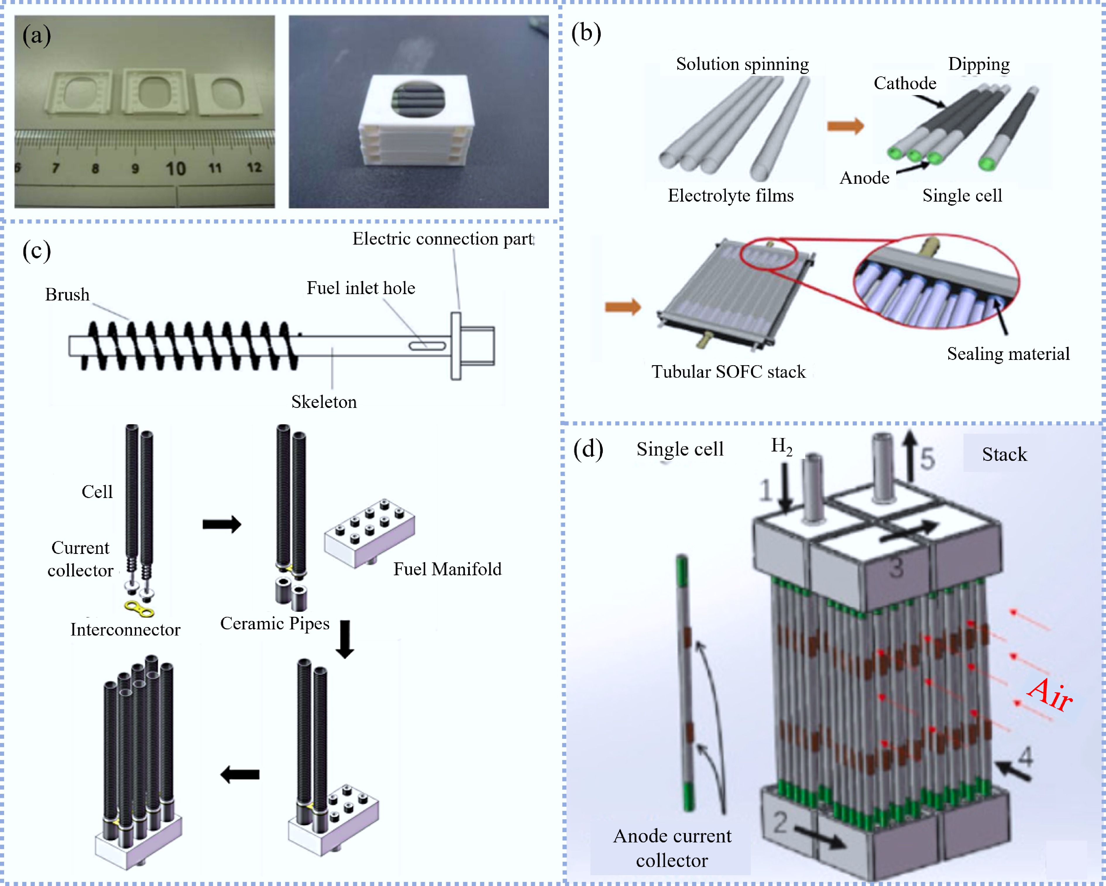
Figure 7.
(a) Actual images ceramic manifold components and micro-tubular SOFC stacks consisted of four bundles[94]. (b) Fabrication process of the MT-SOFC stack Using MgO matrices[61]. (c) Schematic diagram of the current collector and the assembly process of the eight-cell stack[98]. (d) Actual images of the MT-SOFC with double Ni-pads and the schematic diagram of the MT-SOFC stack consisting of 80 cells[99].
Zhang et al.[98] utilized metal current collectors and interconnectors to fabricate MT-SOFC stacks. The schematic diagram of the current collector and the assembly process of the eight-cell stack are shown in Fig. 7c. A metallic rod was inserted into the cell with metal brushes in contact with the interior anode surface to collect current. The eight-cell stack provided 17.3 W peak power at 750 °C, which was lower than the expected value due to the high ohmic impedance of the collector and because the actual test temperature was lower than the setting temperature. The temperature gradient between the anode inlet and the fuel leads to high thermal stress. In order to avoid collecting current from the anode inlet, which can cause destruction to the cell, Liang et al.[100] set up a rectangular current collection window in the middle of the anode and used silver pads for electrical connections. Simultaneously, ceramic/glass paste was used for sealing. The final eight-cell stack produced 24.1 W peak output power at 700 °C. To enhance the current collection, the single Ag-pad design was replaced with a double Ni-pad for more efficient current collection, as shown in Fig. 7d[101]. The maximum output power of the 160-cell stack exceeded 1 kW at 700 °C, which was approximately eight times the performance of the 20-cell stack. Therefore, it can be seen that this current collection method was highly effective. Simultaneously, in order to alleviate the high ohmic loss caused by the tubular structure, 3D printing technology was applied to fabricate interconnectors made of stainless steel 316[102]. An interconnector was used to connect two single cells in series. To evaluate the interconnector, a single cell was cut into three sections and then connected through the interconnector. The peak power density of the cell was doubled compared to cells with the same axial length.
-
As an efficient energy conversion technology, SOFCs are gradually receiving widespread attention. In recent years, the progress in cell performance and stability has promoted the application of SOFCs, both as an independent power generation device and as part of an integrated system. As the main type of SOFCs, tubular SOFCs have been widely used in various fields. This chapter introduces the application of tubular SOFCs, and the collected literatures included the type of SOFCs not introduced in the literature.
Tubular SOFCs for transportation
-
Transportation causes a large amount of carbon dioxide emissions every year. However, decarbonizing transportation is extremely challenging due to the fact that it is difficult to find suitable fuels to replace traditional hydrocarbons. In this background, as technology continues to advance, SOFCs have gained attention as a promising solution. Conventional SOFCs have displayed some major limitations for transportation application such as high working temperatures and slow start-up/shut-down. Additionally, SOFCs feature fragile ceramic components, which pose additional challenges. However, with advancements in materials and cell design, these issues have gradually been mitigated, paving the way for the exploration of SOFCs in various modes of transportation.
A 1 kW SOFC stack on an all-terrain vehicle was installed by Atrex Energy[103], demonstrating stable performance and and only one-third of the fuel consumption of the conventional vehicle during a 3.7 km off-road test loop. Furthermore, no NOx emissions were detected when CNG was used as the fuel, demonstrating the potential of tubular SOFC in transportation. Jaspers et al.[104] proposed a negative CO2 emissions method for transportation based on SOFCs electric vehicles. By utilizing carbon-neutral biofuel, the CO2 produced at the anode was condensed and stored in a pressurized tank for further utilization, thereby achieving carbon-negative emissions. This method significantly reduced the environmental impact of exhaust emissions from SOFC electric vehicles when using hydrocarbon fuels.
In addition, SOFCs can be combined with batteries to supply power for vehicles. The system diagram of SOFCs-battery hybrid vehicle is shown in Fig. 8a. The hybrid system can make up for the soft output characteristics of an SOFCs system alone, allowing the system to respond rapidly to load changes[105]. When the power demand of the vehicle increases rapidly, the battery can supplement the insufficient power of the SOFC system. When the SOFCs system can fulfil the power needs, the excessive electricity can be used to charge the battery.
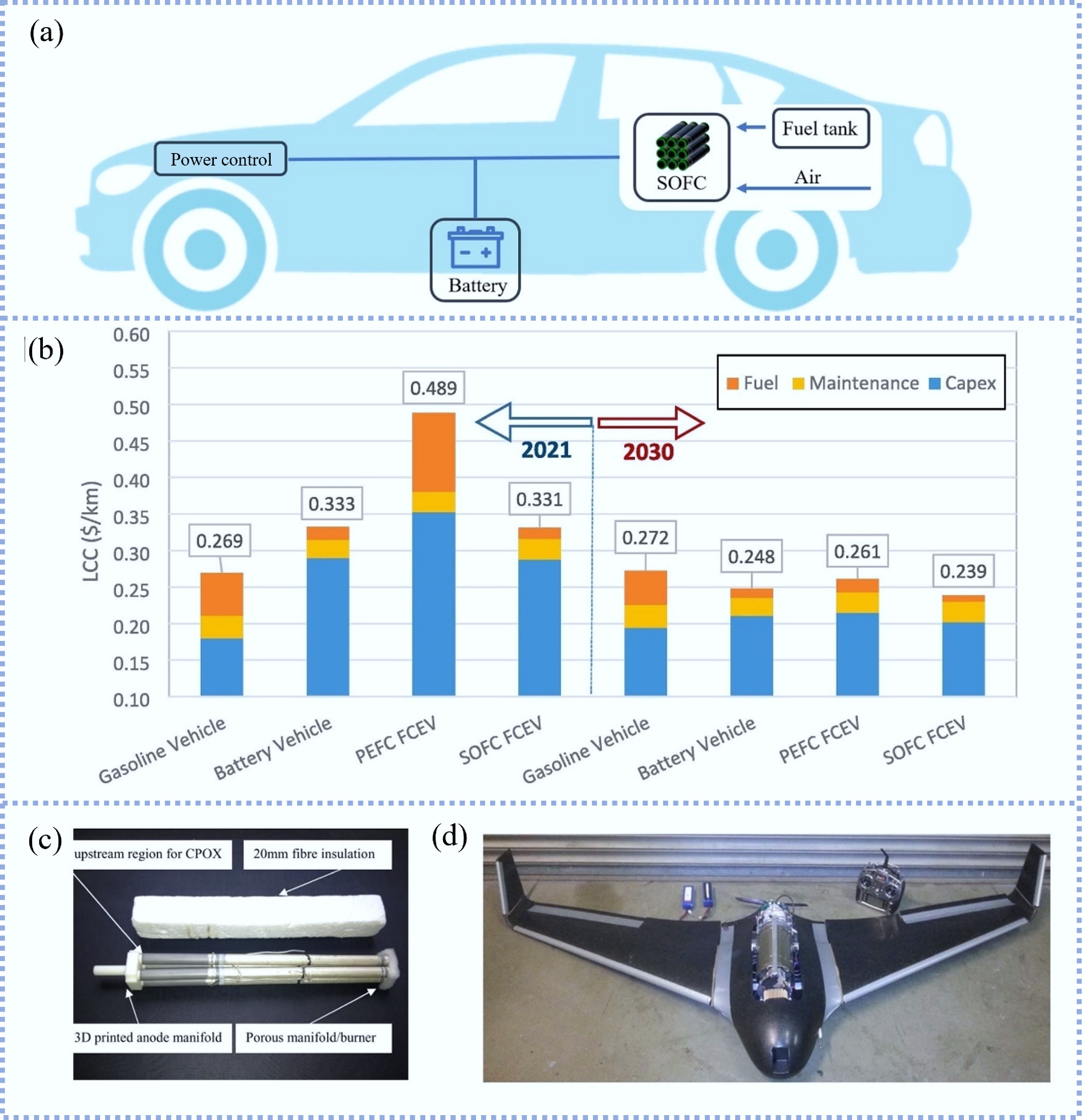
SOFCs-battery hybrid vehicles were compared with battery electric vehicles, gasoline vehicles, and PEMFCs vehicles based on the situation in Iran[106]. As shown in Fig. 8b, considering fuel prices, capital expenditures, operation and maintenance costs, SOFCs hybrid vehicles were the best choice in the future. However, it was worth noting that this conclusion depended on Iran’s abundant natural gas resources and related infrastructure. Bessekon et al.[108] established and verified a model of SOFCs-battery electric vehicles. A 12 kW SOFCs system was integrated into a model of the electric vehicle. The range was significantly increased when using CNG, LNG, or LPG as fuel. Especially, the energy consumption was much lower than that of internal combustion engine vehicles. Therefore, it can be concluded that integrating SOFC with vehicles is highly competitive.
Due to the various advantages of SOFCs, researchers integrated an SOFCs system into the unmanned aerial vehicle (UAV) to develop more advanced power systems, which can significantly increase flight duration compared to battery electric UAVs. Adelan Ltd and the University of Birmingham[107] successfully developed a UAV, the Skywalker X8 UAV, powered by an MT-SOFCs stack and battery as shown in Fig. 8c, d, respectively. The UAV had a wingspan of 2 m and a total weight of 6 kg, of which the MT-SOFC system weighed 2.5 kg. The anode manifold was fabricated by 3D printing technology, which greatly reduced the weight of the MT-SOFCs stack. The SOFC system used liquid propane as fuel, and the catalytic partial oxidation catalyst was positioned inside the MT-SOFCs, which can improve the gravimetric power density of the system but diminish the system efficiency. Finally, the gravimetric power density of the MT-SOFC stack system was 100 W kg−1. Notably, the power required during the takeoff phase of the aircraft was relatively high, which was provided by the SOFCs stack and battery. During cruise or landing, the SOFCs system supplied power, while recharging the battery simultaneously. Ultra Electronics USSI received a
${\$} $ Tubular SOFCs-based CHP system for residence
-
SOFCs are featured by high working temperatures and low noise due to the absence of mechanical components and the ability of supplying power and high-grade exhaust gas simultaneously[112]; they are an ideal option to assemble SOFCs into the CHP systems to utilize waste heat for residential and industrial applications. Figure 9a is the general layout of a typical SOFCs-based CHP system. The power generated by the SOFCs fulfils the requirement of the residence, whereas the excess power could be transported to the grid. When the system cannot fulfil the power needs of the residence, electricity can be purchased from the grid. The waste heat produced by SOFCs is utilized to heat water and supply heat to the residence, as shown in Fig. 9b.
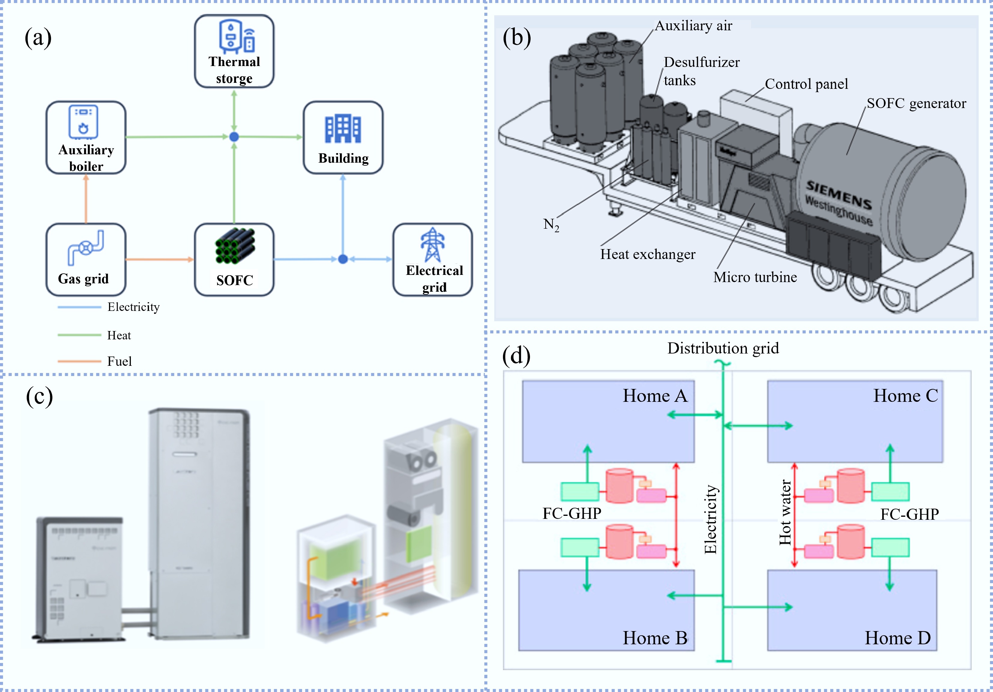
The 100 kW SOFCs-based CHP system developed by Siemens Westinghouse was delivered to EDB/ELSAM (a Dutch/Danish utility consortium) at the end of 1997[115]. The SOFC stack consists of 24 modules containing 1,152 cells and each single cell had an active area of 834 cm2[115]. The SOFCs-based CHP system operated on natural gas as the fuel, delivering 105 to 110 kW of net AC power to the grid and about 65 kW of net AC power to the heating system. An electrical efficiency (net AC/LHV) of 46% was achieved during the spring and summer of 1999.
In 2004, a 1 kW SOFC-based CHP system was developed and installed in a residential setting for demonstration[116]. The SOFCs module consisted of SOFCs stack, heat exchange components and a reforming reactor[117]. During operation, the output power of the SOFCs stack can be automatically adjusted according to the requirements of the residence. Operating at rated power, the electrical efficiency of the system was 49% (net ac, LHV), exceeding the average grid efficiency of Japanese power plants based on fossil fuel. Subsequently, Kyocera, Osaka Gas, Toyota Motor and Aisin Seiki collaborated to develop a new SOFCs-based CHP system. In order to be better suited for in-house installation, the size of the system was significantly reduced by adopting a flat-tubular design, while the rated power of the system was reduced from 1 kW to 700 W. In 2012, the commercialized SOFCs-based CHP system 'Ene Farm type S' was launched, as shown in Fig. 9c[113]. However, the electrical efficiency of the system was 46.5% (LHV). After upgrading, such as improving the air flow in the stack and improving the control accuracy of gas flow, Ene Farm type S (2016 model) exhibited an enhanced electrical efficiency of 52% (LHV)[118].
On the other hand, numerous simulations on the application of SOFCs-based CHP systems in buildings have been conducted recently. Wakui et al.[119] investigated the operation strategy of the SOFCs-based CHP in residential areas. It was stipulated that the power generated by SOFCs can be shared among households within residential areas to form a micro-grid. However, the power produced by SOFC was not allowed to be delivered to commercial power systems. The schematic diagram of micro-grid composed of SOFCs-based CHP in residential area is shown in Fig. 9d. Then, two control strategies of the SOFCs-based CHP system were compared, namely prioritizing power demand and hot water demand, respectively. Based on the data from 20 households, it was concluded that strategy one can improve the electrical load factor of the system and have a high energy-saving effect. Meanwhile, maintaining the high efficiency of power generation in SOFCs-based CHP system was crucial for the competitiveness of the system during power exchange. Pirkandi et al.[120] investigated the effect of working conditions on the SOFCs-based CHP system through simulation. The results showed that raising the working temperature of the SOFCs was beneficial to the electrical efficiency of the system but the thermal efficiency was reduced. Increasing the working pressure had the opposite effect but both strategies can improve overall system efficiency. It was also concluded that when residence units required high electrical loads and low thermal loads, SOFCs with higher operating temperatures should be given priority. Baniasadi & Alemrajabi[121] established a model of a 215 kW SOFCs stack combined with a recovery cycle to fulfil the living needs of a hotel with an area of 4,600 m2, while the energy and exergy analyses of the individual components were conducted. The results showed that the system can achieve a peak efficiency of 83% for simultaneous power generation and heat recovery cycles. Moreover, the system can fulfil all power and cooling load as well as 40% of the hot water demand. In the latest studies, Narayanan et al.[122] simulated the integration of SOFCs-based CHP systems using natural gas as fuel and other energy systems to fulfil the energy needs of residential buildings. The results showed that achieving 100% self-supply of the electrical loads through SOFCs-based CHP was possible. Yang et al.[123] investigated the operation of SOFCs and micro-CHP systems in residential applications in five distinct climate zones in China. The results showed that it was difficult to meet the thermal demand of residences in cold areas with the SOFCs-CHP system, necessitating the use of auxiliary equipment. Fong et al.[124] used numerical simulation to evaluate a 2 kW SOFCs-based CHP system for a residential building in Hong Kong (China), showing a reduction in primary energy utilization and carbon dioxide emissions compared to traditional systems. In general, SOFCs-based CHP system exhibited high energy efficiency and was environmentally friendly. However, in some cold areas, it is a challenge for the small-scale SOFCs-based CHP system alone to meet the power and heat demand.
Tubular SOFCs integrated with gas turbines
-
In addition to CHP system, the high-grade waste heat could be adopted by gas turbines (GT), which improves the overall energy utilization of the system. According to different working pressures, SOFCs-GT systems are mainly divided into ambient pressure systems and pressurized systems. The SOFCs-GT system exhibits high reliability and stabilizes the turbine inlet gas temperature when operating under ambient pressure. Nevertheless, operating under pressurized conditions allows for higher efficiency[125]. Park & Kim[126] established a model to compare the performance of two types of SOFCs-GT systems. The results indicated that the pressurized SOFCs-GT system exhibited superior efficiency, while the efficiency of ambient pressure hybrid systems with a high pressures ratio may be lower than that of the SOFCs only system. Therefore, the pressurized SOFCs-GT system is used in most cases.
Figure 10a is the schematic diagram of a pressurized SOFCs-GT system. The air is compressed to the working pressure of the SOFCs and then heated by a heat exchanger. The pre-heated air enters the SOFCs stack, where it reacts electrochemically with the compressed fuel to produce electricity. The cathode exhaust gas and remaining fuel are completely burned in the combustor and then enter the turbine. The airflow expands inside the turbine, driving the generator to produce electricity. The exhaust gas from the GT is delivered to the heat exchanger, thereby improving energy efficiency.
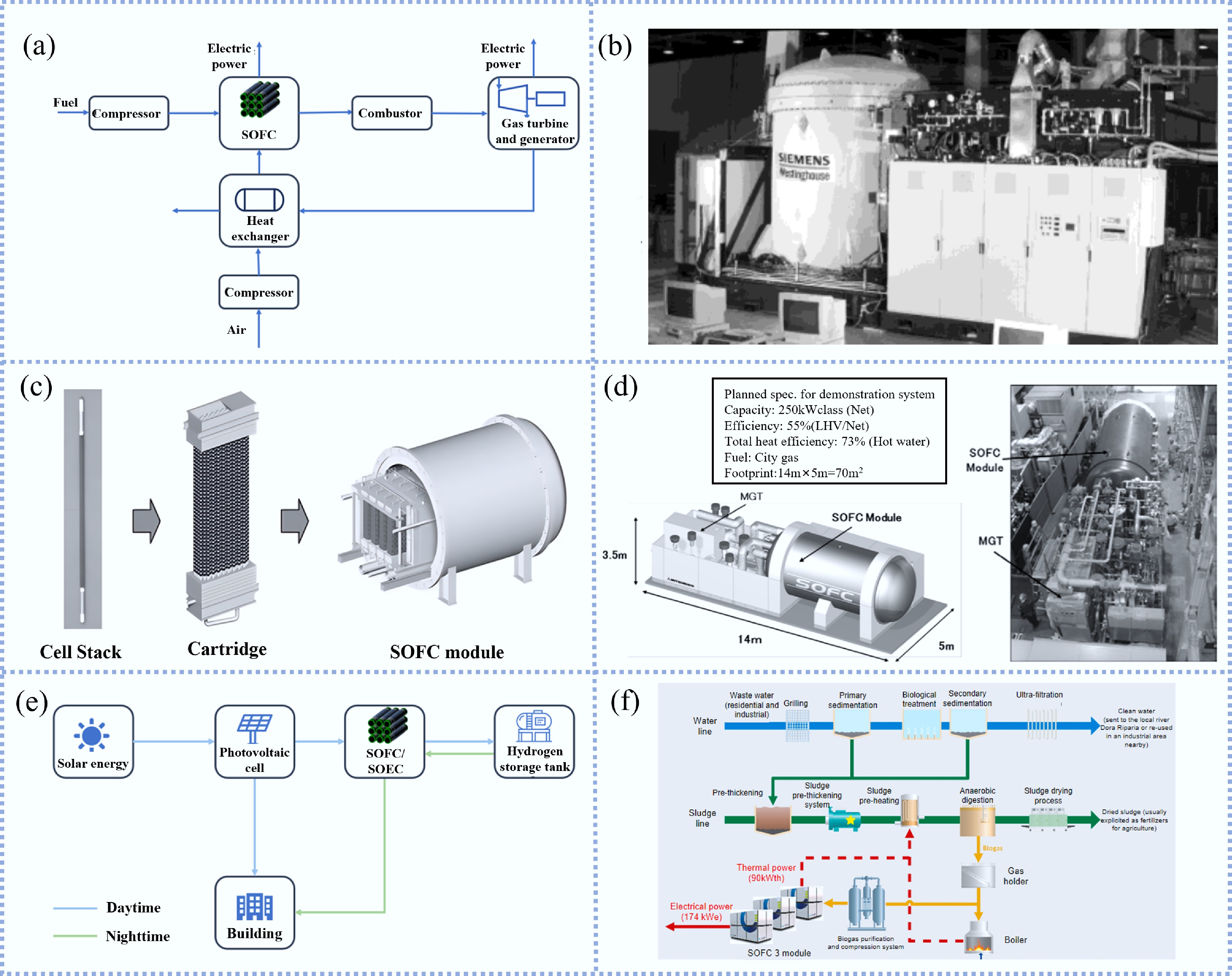
Figure 10.
(a) Schematic diagram of a pressurized SOFCs-GT system. (b) 220 kW SOFCs-GT system without the power dissipators[19]. (c) SOFC module developed by MHI[127]. (d) 250 kW SOFCs-GT system was developed by MHPS[66]. (e) Schematic diagram of a system combining SOFCs and photovoltaics. (f) Layout of wastewater treatment plant with SOFCs[128].
In 1997, SCE signed a contract with Westinghouse Electric to manufacture a SOFCs-GT system[115]. A 220 kWe power system based on tubular SOFCs stack consisted of 1,152 cells, with a cell diameter of 22 mm and a length of 1,500 mm, connected in series/parallel. In addition to the SOFCs module, the SOFCs-GT system also included four main modules: fuel supply, electrical and power dissipation devices, thermal management (including micro-turbine generator) and heat export. The system without the power dissipator is shown in Fig. 10b. With natural gas as the fuel, SOFCs module operated at pressurized condition of 3 atm. During initial testing, the total power of SOFCs and MGT DC was 166 and 22 kW, respectively[126].
Mitsubishi Heavy Industries (MHI) manufactured and tested a 200 kW SOFCs-MGT system based on the SIS-SOFC stack and the SOFC module is shown in Fig. 10c[127]. The system achieved the peak power of 229 kW-AC and the peak efficiency of 52.1% LHV. The system remained stable for 3,224 h. Subsequently, Mitsubishi Hitachi Power Systems (MHPS) further manufactured a 250 kW SOFCs-MGT system, as shown in Fig. 10d, and conducted various practicability evaluation tests to test system performance[66]. The results indicated that the electrical output power of the system was approximately 204 kW and the power generation efficiency reached 53.6% LHV during rated-output operation. During the 25,000 h of rated-output operation, the SOFCs stack remained stable after repeated start-up/shut-down. Moreover, the system exhibited the ability to efficiently recover waste heat with a total efficiency of 74.1% LHV, so it had excellent potential for energy saving and emission reduction[129].
In addition, numerous theoretical studies on the SOFCs-GT systems have been reported. Zhang et al.[130] conducted research on the rapid load switching of the SOFCs-GT system to ensure stability of the grid when renewable energy was integrated. Bypass valves were set up to regulate the flow of SOFCs cathode gas during load switching, while the fuel utilization was sustained by changing the fuel flow. The pre-combustion and after-combustion chambers were set up to balance heat requirements. With these control strategies, a 50% load change can be achieved in just 10 s while protecting the SOFC stack. Lai et al.[131] conducted a cradle-to-product life cycle study of four types of SOFCs power plants to understand the life cycle environmental impacts of the SOFCs applications in the systems. The results indicated that the SOFCs-GT hybrid plant with steam cycle was considered the optimal alternative, while it was also concluded that operating the SOFCs stack in constant voltage mode will extend the service life of the SOFCs stack compared to constant power operation. van Biert et al.[132] analyzed four SOFCs combined cycles and showed that pressurized SOFCs-GT systems exhibited higher electrical efficiency at high temperature and moderate cell voltage. On the other hand, the SOFCs-steam turbine combined cycle was more competitive at low temperature and high cell voltage. Sghaier et al.[133] established a thermodynamic and electrochemical model containing SOFCs-GT, conducted a parameter study on SOFCs-GT, and pointed out that an increase in ambient humidity and temperature will reduce the efficiency of the power plant.
Tubular SOFCs integrated with renewable energy
-
As typical types of renewable energy, solar power and wind power suffer from intermittency issues, which necessitate their integration with other technologies for uninterrupted power supply. SOFCs/SOECs have gained attention as a promising solution due to their flexible reversibility. By optimizing the system design, SOFCs exhibit excellent load-reactive capabilities[134]. Moreover, SOFCs can maintain high-efficiency under partial load, which is relatively difficult with gas turbine[135]. Figure 10e depicts the schematic diagram of a system combining SOFCs and photovoltaics. During the day time, solar energy is converted into electricity through photovoltaic cells, with excessive power used to produce hydrogen through the SOECs while meeting the electricity demand. When solar radiation is insufficient, a stable power supply is ensured through the SOFCs system. In this way, the hybrid system based on photovoltaic power generation system and SOFC achieves all-weather power supply.
Xi et al.[136] integrated solar chimneys and SOFCs into a system, the electricity was generated through solar chimney operation during the day time, and excessive power was used to produce hydrogen through the SOECs. When solar radiation was insufficient, the solar chimney cannot fulfil the power demand and the SOFCs started to generate electricity. The integrated system made up for the limitation that the solar chimney cannot work at night, achieving long-term continuous power supply. Shariatzadeh et al.[137] utilized the same strategy to compensate for the shortcomings of photovoltaic systems that cannot continue to work.
Apart from generating electricity through photovoltaic cells, solar energy can be used to fulfil thermal demand. Gandiglio et al.[128] coupled SOFCs with a wastewater treatment plant, and the plant floor plan is shown in Fig. 10f. The biogas generated by the anaerobic digester was converted into fuel through the reformer and then entered the SOFCs stack for power generation. The heat discharged from the SOFCs stack was recovered to fulfil partial heat demand of the anaerobic digester, while the concentrated solar thermal system also supplied heat to the digester. In the life cycle impact assessment (LCIA), the biogas-fed SOFC cogeneration modules reduce the environmental burden associated to WWTPs with a substantial share of electrical energy (around 25%) production. Azadi[138] established a system model to produce methane and hydrogen utilizing solar collectors coupled with the catalytic hydrothermal glycerol reforming. The heat required in the process of the catalytic hydrothermal reforming of glycerol was provided by the solar collector. After removing water, the generated gas can be used as fuel for SOFCs. Moreover, when using other oxygenated biomass compounds, only minor change to the system were required. In addition, there are research works on SOFCs integrated with wind power system[139−141], and microgrids composed of SOFCs and renewable energy[142,143].
In general, the system coupling SOFCs and renewable energy dramatically extends the range of SOFC application. Meanwhile, the integrated system effectively addresses the long-existing intermittency issue of renewable energy, which enables stable and continuous operation.
-
In conclusion, tubular SOFCs technology offers distinct advantages and significant prospects compared to traditional fossil fuel-based power generation. This review has systematically introduced the manufacturing processes, stack assembly designs, and application status of tubular SOFCs. The main conclusions are summarized as follows:
1. Geometric optimization: Each geometric configuration possesses unique advantages suitable for specific applications. FT-SOFCs offer higher volumetric power density, making FT-SOFCs advantageous for stationary power generation (kilowatt level), though sealing remains a key limitation. Both SIS-SOFCs and cone-shaped SOFCs achieve higher voltages in limited spaces but face challenges in interconnection integrity. To date, while the FT and SIS stacks have reached the kilowatt level, scaling to the megawatt level requires overcoming these structural hurdles. Conversely, MT-SOFCs, with their high specific surface area and rapid start-up capabilities (exceeding 2 W cm−2), are ideal for portable and UAV power systems. A major challenge for MT-SOFCs lies in optimizing current collection for kilowatt-class scaling.
2. Fabrication advances: The fabrication process critically determines cell performance. While extrusion method and phase inversion are the mainstream methods allowing for single-step multi-layer preparation, phase inversion offers superior control over the internal pore structure of the support. Future development should focus on refining these processes to reduce sintering costs and enhance mass transport properties.
3. Integration and waste heat utilization: Tubular SOFCs can be used as independent power units due to their mechanical robustness and thermal shock resistance. Additionally, their high grades waste heat offers significant opportunities for integration with other systems (e.g., CHP or gas turbine), which is essential for improving overall system efficiency and economic viability.
4. Future perspectives: Reversible operation and hydrogen production: In future development, the utilization of SOFCs waste heat will become a key research focus to further enhance the energy efficiency and economy of the system. The operation of tubular cells in reversible mode (r-SOC) for green hydrogen production and energy storage is a critical research frontier. Tubular designs are intrinsically well-suited for r-SOC applications due to their high mechanical strength, which can withstand the high pressures required for efficient electrolysis, and their simplified sealing which mitigates gas leakage risks. However, several specific technical challenges remain:
Electrode stability: Long-term degradation of the air electrode under high steam concentrations (in electrolysis mode) needs to be addressed through novel material design.
Thermal management: Efficient thermal management strategies must be developed to handle the transition between exothermic (fuel cell) and endothermic (electrolysis) modes to prevent thermal stress accumulation.
System response: Improving the dynamic response rate of the stack to couple effectively with intermittent renewable energy sources (solar/wind) is crucial for achieving grid-level energy storage and carbon neutrality.
-
The authors confirm their contributions to the paper as follows: Tong Wang: conceptualization, writing – original draft, writing – review & editing; Yanling Feng: visualization, revising – original draft; Yeqing Ling: visualization, resources; Bin Wang: investigation, methodology; Yakun Wang: conceptualization, resources; Mohd Hafiz Dzarfan Othman: investigation, methodology; Tao Li: conceptualization, funding acquisition, project administration, resources, writing – review & editing. All authors reviewed the results and approved the final version of the manuscript.
-
Data sharing is not applicable to this article as no datasets were generated or analyzed during the current study.
-
This research was funded by the National Natural Science Foundation of China (Grant Nos U24A20542, 52276175), and the Natural Science Foundation of Jiangsu Province (Grant No. BK20210252).
-
The authors declare that there is no conflict of interest.
-
Systematically reviews advanced fabrication techniques for diverse tubular SOFC geometries.
Critically analyzes state-of-the-art stack designs, assembly strategies, and technical bottlenecks.
Highlights diverse application scenarios ranging from portable power units to integrated hybrid systems.
Proposes geometry-specific development roadmaps and future perspectives based on intrinsic cell characteristics.
-
# Authors contributed equally: Tong Wang, Yanling Feng
Full list of author information is available at the end of the article. - Copyright: © 2026 by the author(s). Published by Maximum Academic Press, Fayetteville, GA. This article is an open access article distributed under Creative Commons Attribution License (CC BY 4.0), visit https://creativecommons.org/licenses/by/4.0/.
-
About this article
Cite this article
Wang T, Feng Y, Ling Y, Wang B, Wang Y, et al. 2026. Geometric design and application exploration of tubular solid oxide fuel cells. Energy & Environment Nexus 2: e009 doi: 10.48130/een-0026-0001 

Geometric design and application exploration of tubular solid oxide fuel cells
- Received: 07 November 2025
- Revised: 24 December 2025
- Accepted: 12 January 2026
- Published online: 28 February 2026
Abstract: Solid oxide fuel cells (SOFCs), as promising and efficient power generation devices, can play an important role in addressing the energy crisis and environmental challenges. Among various cell architectures, tubular SOFCs are distinguished by their exceptional thermal shock resistance and simplified sealing requirements, making them highly suitable for robust long-term operation. This review presents the development status of tubular SOFCs with different geometries, covering the manufacturing methods and stack assembly designs. It is concluded that while conventional tubular designs offer mechanical robustness, flat-tubular geometries provide superior volumetric power density essential for stationary stacks, whereas micro-tubular architectures are uniquely suited for portable applications due to their rapid thermal cycling capabilities. Furthermore, the review outlines the current status of tubular SOFCs integrated with other systems, such as in transportation applications, combined heat and power (CHP) systems, and gas turbines. These integrations demonstrate the potential of tubular SOFCs in promoting sustainable energy utilization. Finally, future development directions are proposed based on the specific characteristics of these tubular configurations.
-
Key words:
- Tubular SOFCs /
- Geometry design /
- Fabrication technique /
- SOFC application